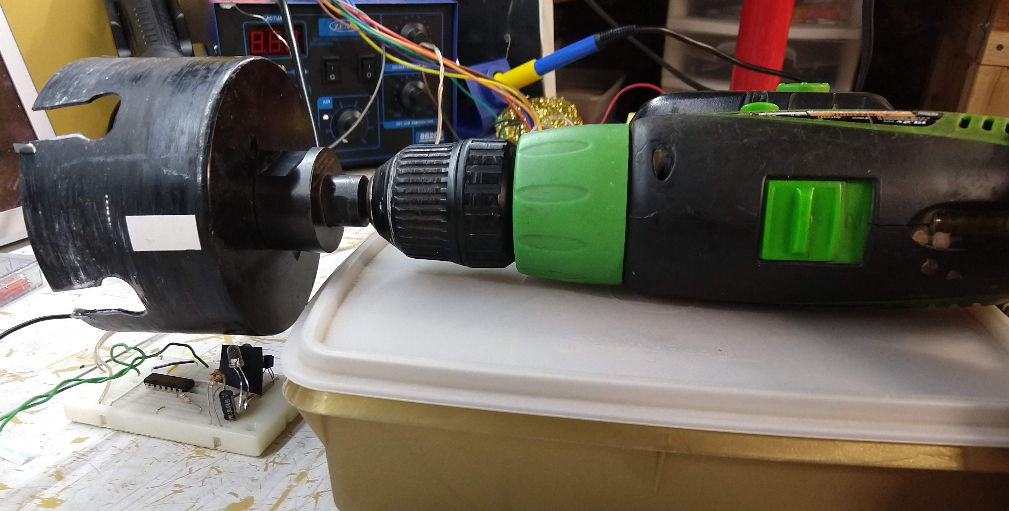
I find myself in need of a tachometer, for my lawnmower. Why? Well, I generally don’t worry too much about little things like reasons and justification. Let’s just say that this lawnmower has been a small heap of trouble and any diagnostic may be useful.
So, here’s what I’m working with, a Poulan Pro PR25PH48ST with a Briggs and Stratton 445777.

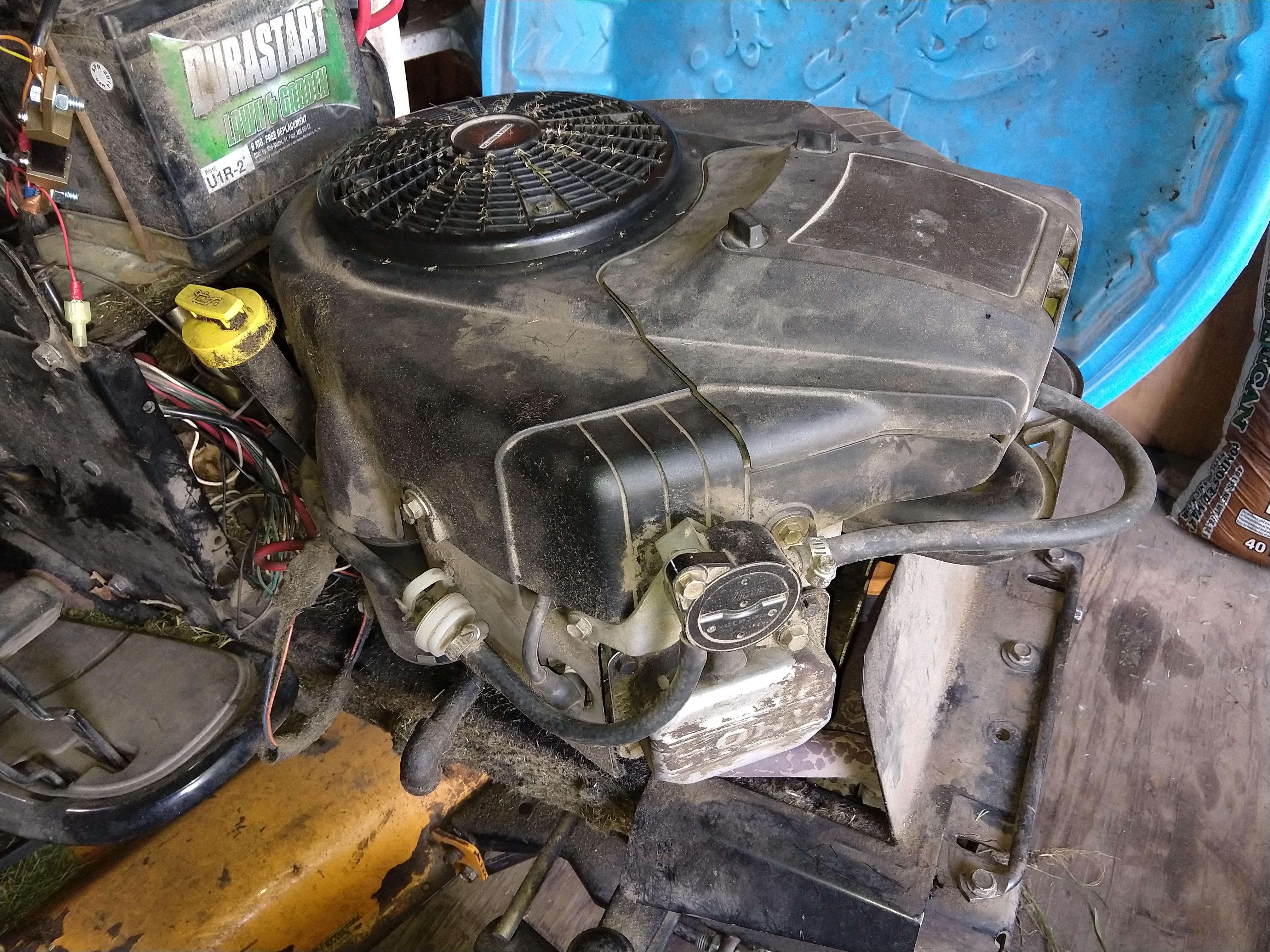
Now I’ve just got to think up a way to determine the engine’s RPM; I suppose I have a few options. I could monitor the output of the alternator, but that is likely one of the problem components, so I can’t consider it’s output correct. I should be able to monitor engine noise and determine the RPMs via some spectrum analysis, but that seems like more Math than is good for my health. Barring some other options not coming to mind right now, that leaves actually watching the spinny-bits do their thing.
Let’s see here, I could add the sensors at the crankshaft output on the bottom, however, that puts my—likely sketchy—sensor setup very near the sharp parts and the hot parts. I’d rather not do that, so, I suppose that leaves the impeller on top.
I’m going to stay away from physically connecting a rotary encoder1, and prefer non-contact methods; they are generally less likely to disintegrate into missiles.
I’ll start with considering Hall Effect sensors. Adding a sensor next to the impeller and securing a magnet2 to it could certainly work for determining rotational velocity. However, this also seems like it could also result in me having a magnetic abdomen; I strongly prefer myself to remain un-punctured. There’s also a concern that directly under the impeller is the alternator, so I’d bet on some magnetic interference.
Then maybe some light, how about shining a beam through the impeller and using the breaks in the beam caused by the blades to determine crankshaft speed?3 I don’t actually see many downsides to this, other than keeping the light source and detector aligned with all the engine vibrations. I may come back to this later. Sticking to light methods, I’ll take an idea from the ol’ Intro to Embedded Control syllabus. Remember that car that follows a line? The idea is that there’s a high-contrast line on a surface and the car would use infrared LEDs and photo-transistors to know when it was over the line4. Since the impeller is black (maybe just very dirty, who knows?) a white mark could be added to it and that could be detected as it spun past the sensor.
Cool, I can work with this. Now, I just have to remember some electric circuits knowledge. Good thing I (barely) passed that class5. I’ve conveniently had an IR LED and phototransistor sitting around in a box since I bought them from Radio Shack around 20026. After selecting resistors with values given by the well-known Google Said So Method, I’ve got this:

Simple, eh? Too bad it’s not really what I want. What I really want is a nice, simple, high signal means the white mark is in front of the sensor, low signal means it isn’t (I’ll also accept the inverse of that). This results in something more like this:
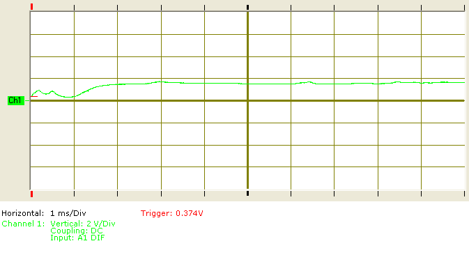
What you see here is the signal rising as my test setup7 transitions off of the white mark. Way too much in-between and squiggly-ness. Ok, so I suppose I could just hook this up to an analog input and sort it all out in code, but that is starting to sound an awful lot like the M-Word. I also haven’t completely decided on what the controller will be yet, so, I’ll just try to keep those requirements to a minimum for now.
A few things need to be done to this signal. First, we need to smooth it out, then we’ll need to make it more digital-y with logic levels the rest of our hardware can understand (TTL seems like a good assumption for now). First off, I’m going to guess that I could re-purpose a switch debouncing circuit for the smoothing purpose. This is a convenient assumption because I already have this circuit on a breadboard from when I was testing my oscilloscope. I’ll just add the phototransistor to it like this:

Cool, cool, now my signal is rather more reasonable:
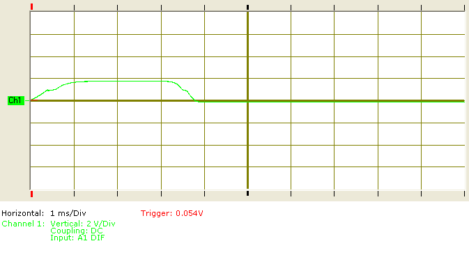
I’d prefer a high somewhat closer to 5V, but maybe I’ll worry about that later8.
Hrm. you know how I said I’d got those parts from Radio Shack 15 years ago? Well, around that time I also picked up some handy-dandy little books in their Engineer’s Mini Notebook series9, and in Electronic Formulas, Symbols and Circuits (page 151) there is a whole page of phototransistor schematics. Apparently, I’m on the right track, some of these are familiar, and one looks like where my brain was heading.
I could add an op-amp in here to boost the signal some, but I’ll just put it through a logic chip of some kind or other10. Thankfully I purchased a semi-random selection of 74-series chips several years back, for reasons lost in the mists of memory. I also have a fairly large selection of chips that have been liberated from their former occupations. Using a 7404 hex inverter from my Digikey-binge (note I only purchased HCT subfamily chips8) connected like this:

I get results like this:
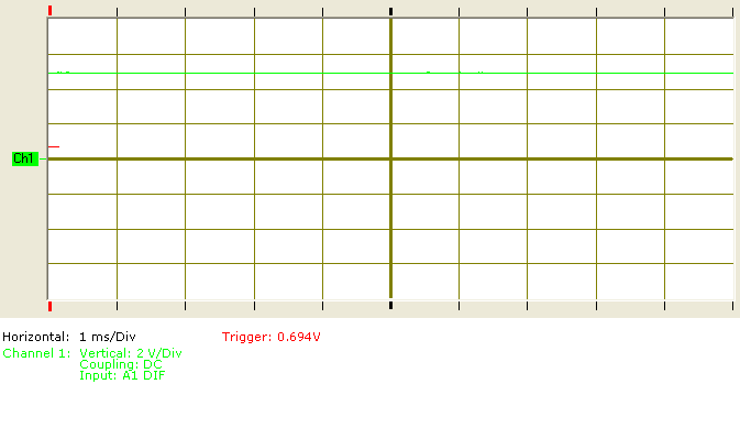
GAH.
OK, so. I know what happened. When I purchased these chips I selected HCT for the best compatibility between CMOS/TTL/whatever. Unfortunately, the minimum high input voltage for 5V HCT is just above 3V, and as you saw, our high output is around 2V. I could fix this in a few ways. I could use an op-amp like I mentioned earlier, I could probably adjust the resistor/transistor, or I could just look in my box of 74-series chips. Whadayaknow, I have here a 74LS04, and I’m a firm believer in the Just Go For It Philosophy.
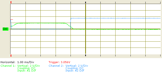
Much better. Note that for added confusion, this one has the important part on Channel 2. The main difference that matters here is that the minimum high input voltage for the 5V LS subfamily is about 2V. This gives me a fairly modular setup translating proximity to high/low logic. I will need to be able to change the sensitivity, and some noise reduction would be good, but this is a good start.
How about one last change.
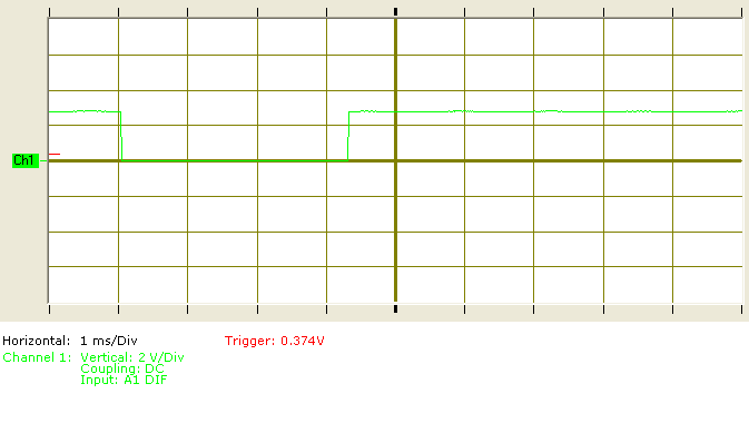
Wow! What did I do? Well, the proximity sensor I ordered from China finally arrived. I’m just going to use that from here on out. Here’s what China decided to use:

They seem to have not bothered with a discreet transistor at all and just used an op-amp instead. There’s also a convenient sensitivity potentiometer, that I would have had to get around to eventually. I think I have an LM393 around here somewhere, so maybe I’ll mess around with replicating this later.
Further Reading
I talked through my thoughts on this project so far, but I didn’t really explain things thoroughly.
If you want to know about how to make an IR proximity sensor, take a look at this Instructable. Also I do highly recommend the books by Forrest M. Mims III.
Actually, it should be possible to paint the impeller itself into an optical rotary encoder and rig some optical sensors—or just a camera—to handle position detection. However, in the style of academia “…this is beyond the scope of The Author, and is left as an exercise for the reader.” ↩︎
There’s a point here that I may come back to it later. Having a single point of reference on the rotation of the crankshaft may be sufficient for determining its average speed, but it does not allow for knowing the current speed and certainly doesn’t give the absolute rotational position. For simply displaying RPMs this does not matter, but attempting engine control—such as EFI—would benefit greatly from knowing with certainty where the crankshaft actually is. Attempting to determine crankshaft position from a single point of reference would require using the previous rotation period to predict the current rotation. This may very well be close enough to work, but I wouldn’t expect it to run terribly smoothly. Though you could improve the prediction by introducing a little calculus, keep track of the rate of change in the period and figure that into the current position calculation; ew, I can feel my Math allergy starting to act up, I’ll avoid that idea for now. ↩︎
Bonus: this would actually (help) solve some of the current speed and position issues mentioned in the previous footnote, as the resolution is proportional to the number of impeller blades. ↩︎
The light source and sensor are placed next to each other, pointed in the same direction. Light from the source bounces off the surface back to the sensor. Depending on how the sensitivity is tuned, this can detect proximity and/or reflexivity. I will be referring to infrared (IR) light for this document, however any matching source/sensor could be used. Different wavelengths would have different interference from the environment. I do have a suspicion in the back of my mind that infrared light may not be the best next to an air-cooled engine. ↩︎
What? ‘D’ stands for ‘Done’. In my defense, analog has never been my specialty, and also there’s that aforementioned Math allergy. ↩︎
In high school I was really into the idea of creating robots, I just never got around to actually doing it. Eventually I may finish comimg to terms with my inability to complete anything. ↩︎
I have a piece of white tape stuck to the side of a spinning black cylinder. Super professional. ↩︎
A collection of little books with schematics and explanations by one Forrest M. Mims III. I have “Timer, Op Amp & Optoelectronic Circuits & Projects”, “Science and Communication Circuits and Projects”, and “Electronic Formulas, Symbols and Circuits”. I would highly recommend these for a young wanna-be Electrical Engineer (or even an old wanna-be). What was unfortunate in my case was that I could afford the books, but I usually was just working with scrap components, so I didn’t always have what was needed. That wasn’t supposed to be a complaint, I had a point; if you get/give a book like this, get/give a kit too. ↩︎
Alright, so, depending upon what I’m connecting this sensor to, having a buffer here may be redundant. Work with me for the sake of explanation, ok? ↩︎