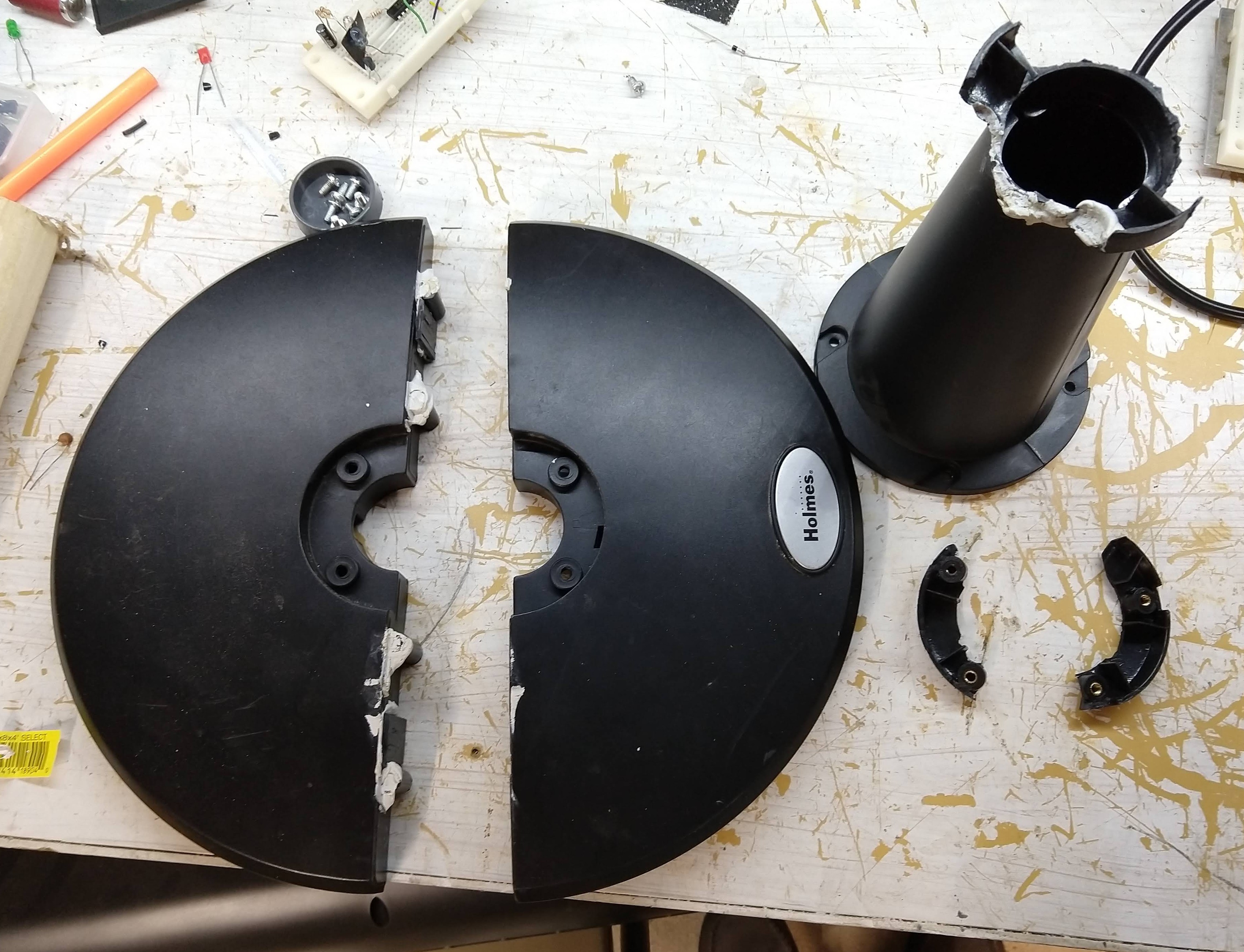
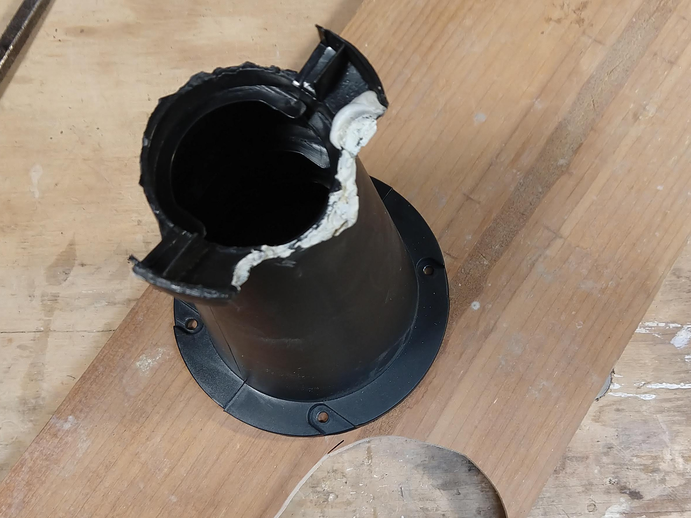
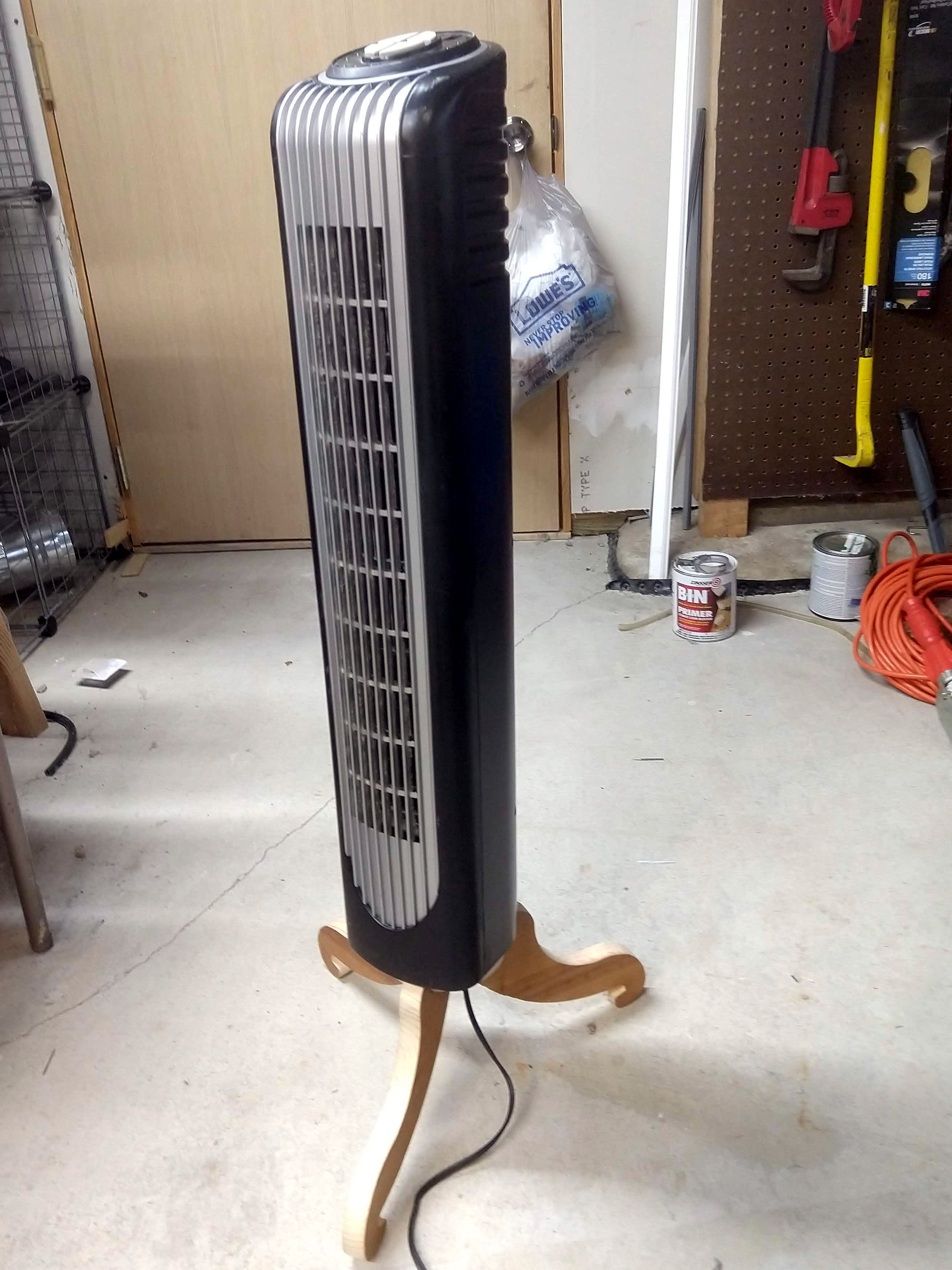
I have a fan. Unfortunately, it’s a broken fan. Apparently the manufacturer did not design it with children in mind. Silly engineers, not factoring in 30 pounds of kid hanging off of it. Well, now it’s base has broken, and been glued back together… then broken again1.
I suppose the simplest solution is to just cut out a cylinder of wood with a hole for the cable, and then screw it to a piece of plywood for the base. I’ve never been one for simple: this stand’s got three legs2, and it knows how to use ’ems. Not any boring, straight legs either, this is gonna be curvy; now if only I could find my French Curve. I’m staring at some Victorianish furniture, so I have a few ideas to work with. With a compass and some measuring I can come up with something.
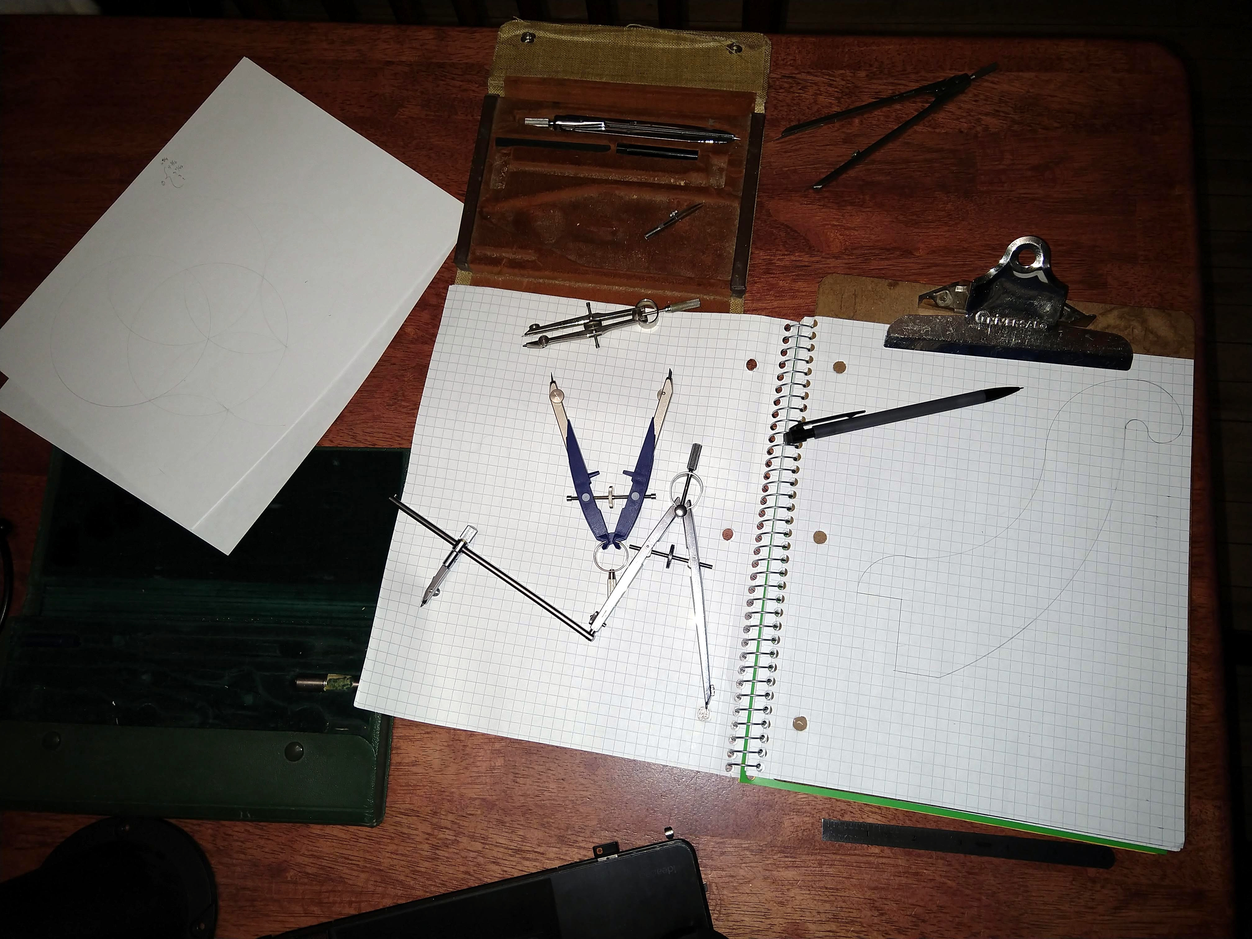
Alight, so this took a few goes to get the size, shape3 and position on the paper correct, but I think this will work. I kinda wanted to do this without CAD, but it’s either that or finding my pad of carbon paper, and I’m pretty sure I lost that ten years ago.
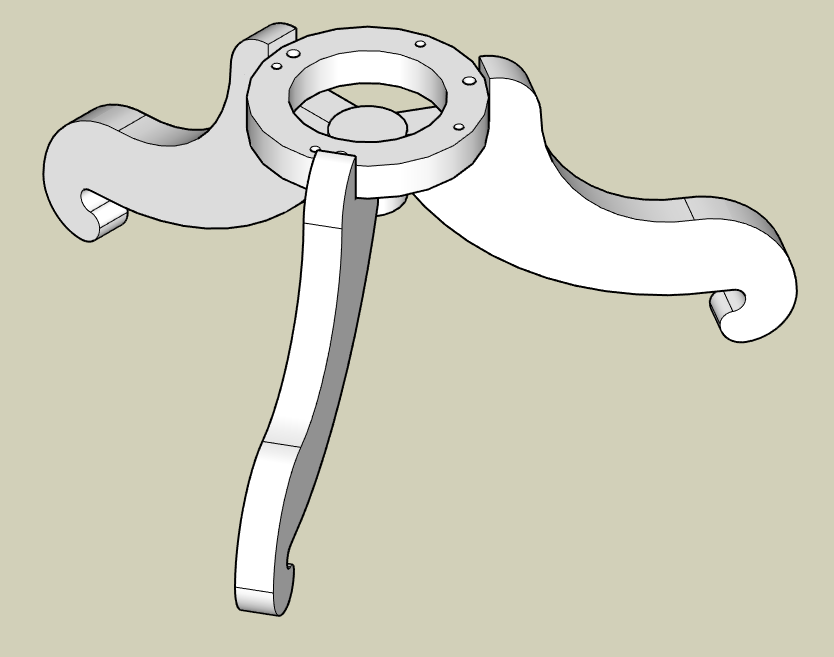
That actually didn’t take too long. There are a few details that I didn’t worry too much about, mostly where the legs connect to the center. That is going to be the weakest point, and also will be the most difficult place to have the surfaces mate. For a perfect fit I’ll either have to flatten or curven something. That’s Future Caleb’s problem.
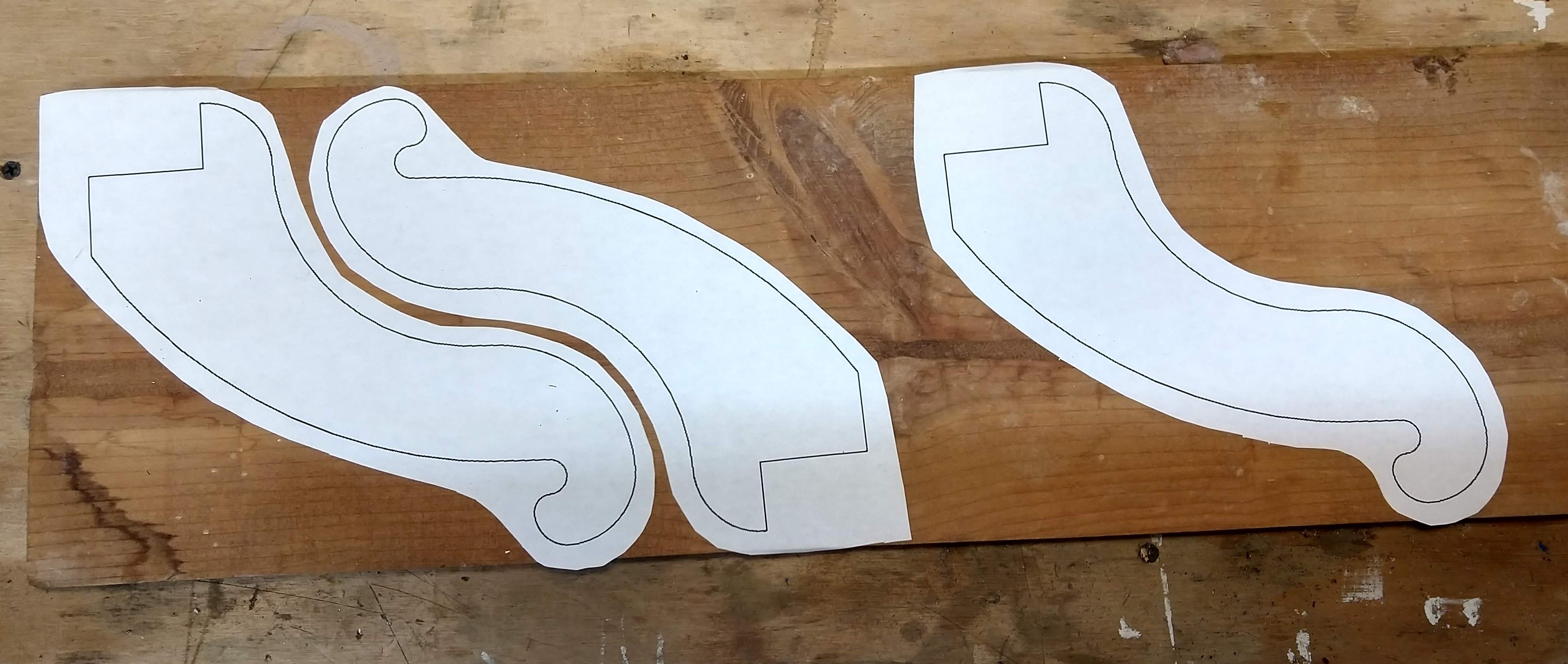
Meanwhile, I’ve got some leg templates printed, found a board, and stolen a glue stick from the kids. I also cleaned off the board with some mineral spirits, it had things on it. I don’t actually know where this board came from, it’s different from the rest of my supplies. I suppose it either came with the house or the Wood Fairy dropped it off.
Now for life’s important question: which direction should the wood grain go? This is likely dependent upon how the legs will be affixed to the center ring; my drawing uses a pin inserted vectically. If I had the grain vertical this would cause a weak spot in parallel with the hole in the leg4. I’ll go with horizontal grain, and try to miss that big knot.
Hopefully this glue is good enough to hold them down, there’s a lot of good vibrations in the future.
I really need to go slower with my scroll saw. It’s times like this when I wish I’d got the small bandsaw instead. My little Ry-slow-bi doesn’t do too well with 3/4" wood (probably better blades could help as well) , I have to creep along carefully or risk the blade bending and ending up with a angled cut. I’ll try to keep the blade a bit clear of the line in case of this, but, eh.
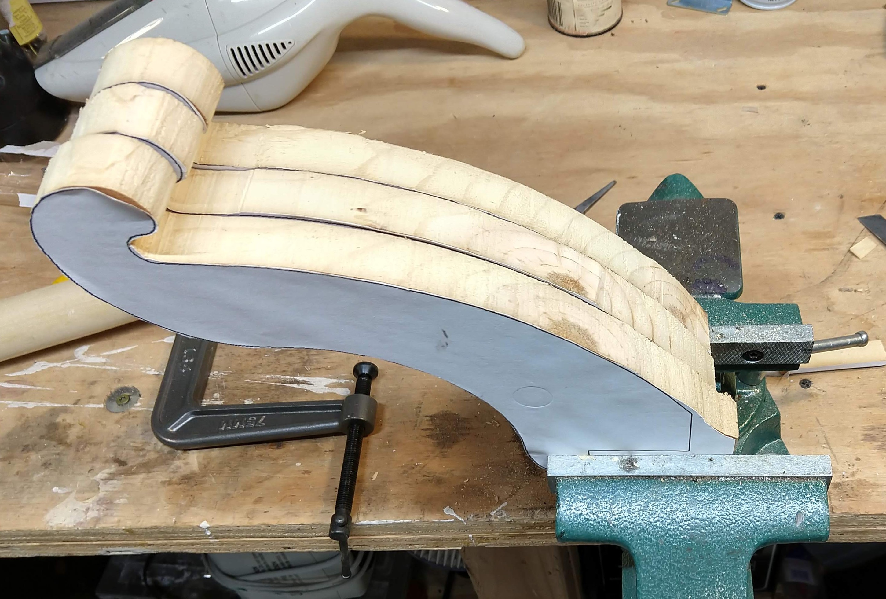
Well within tolerances5. I’ll just have to file them some. Then sand them some.
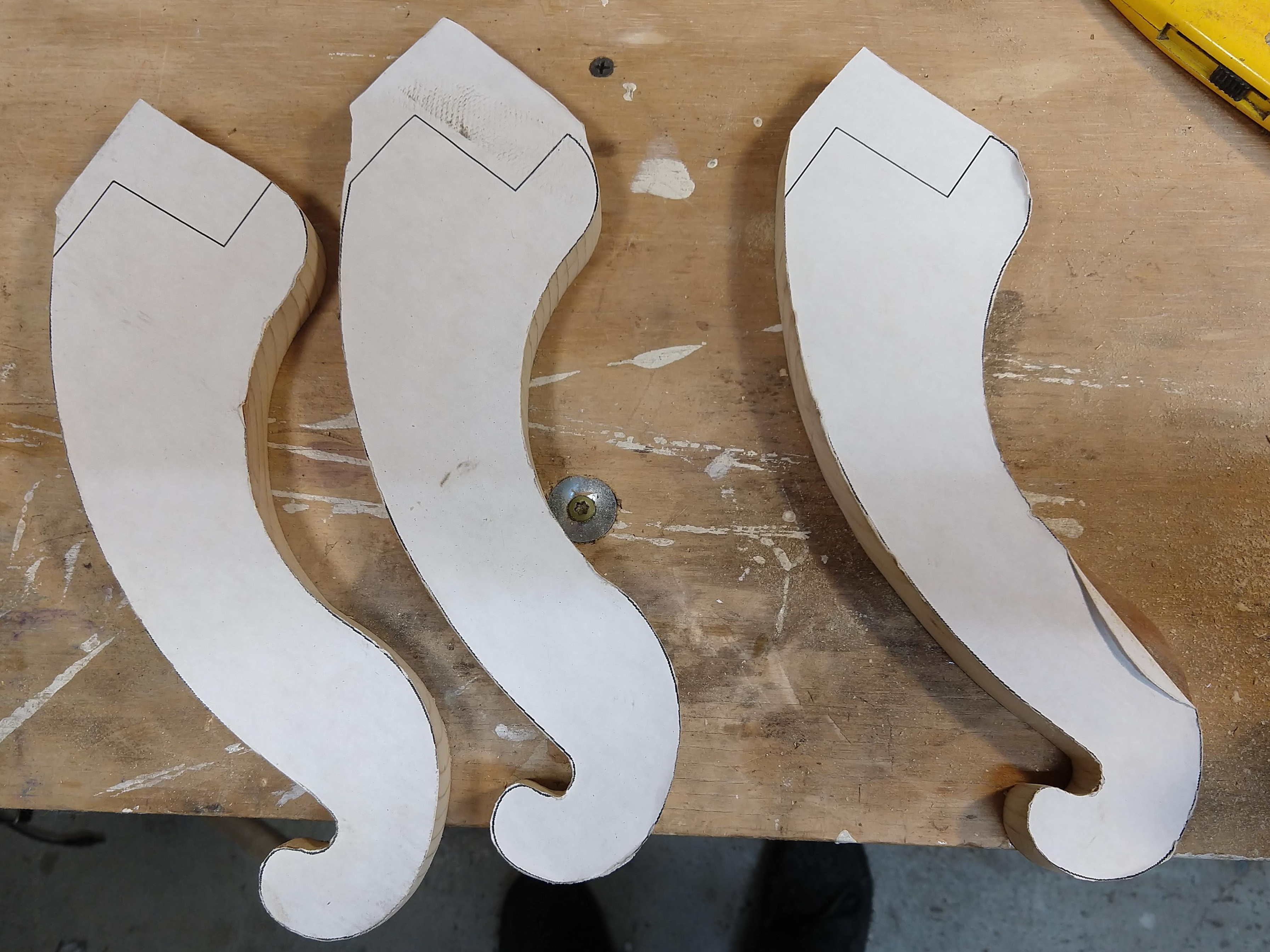
Ta-Da! Yeah, the ends that meet up with the ring aren’t finished yet. I’ll get to that. after I make the ring. Should be easy enough, just trace out the old base and mark where the holes go. Nothing could possibly go wrong.
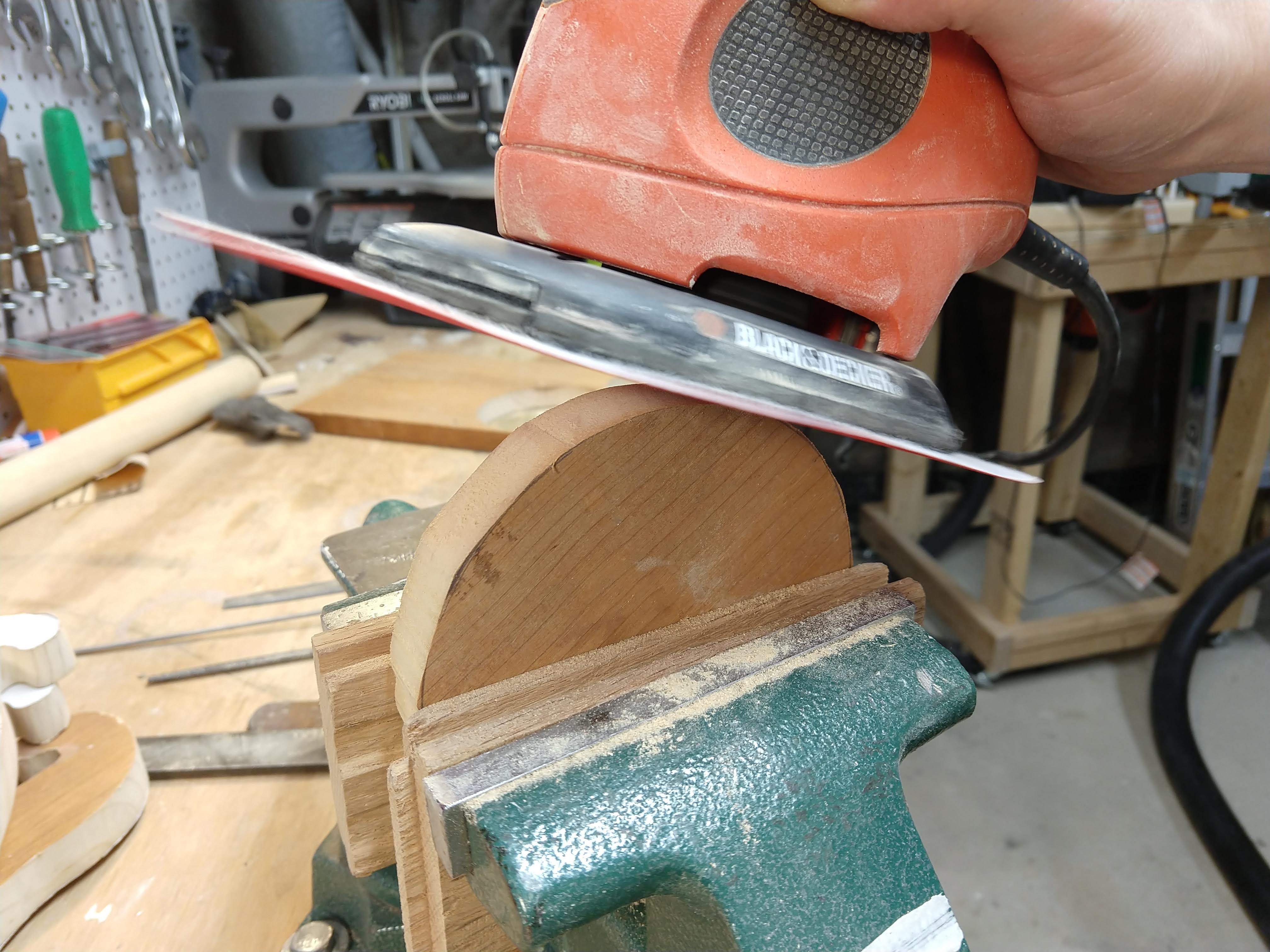
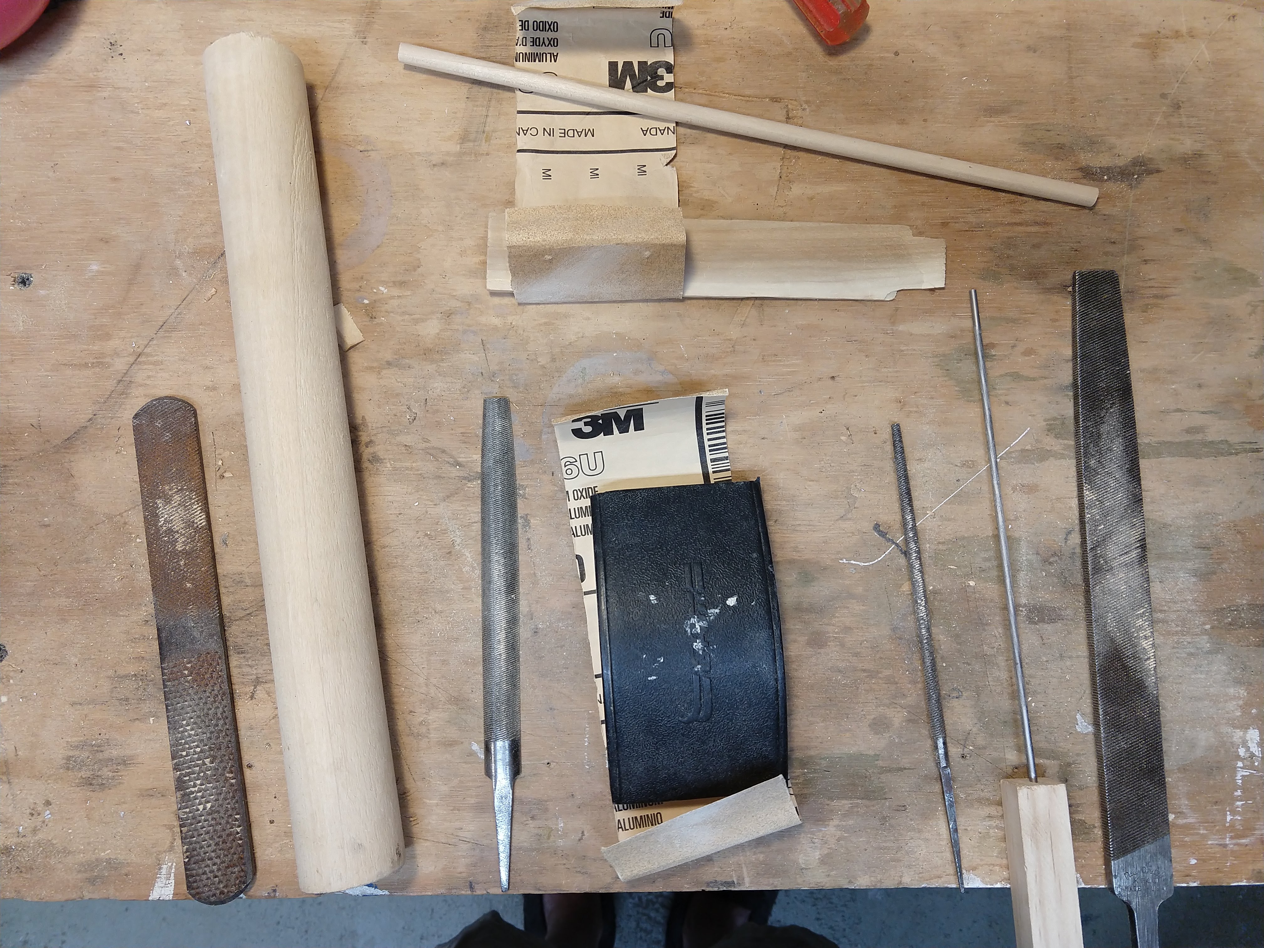
A little scroll sawing, a little sandering. Wait. I have an orbital sander and a belt sander, why the bloody frellin’ frak was I fooling around with files and sandpaper‽
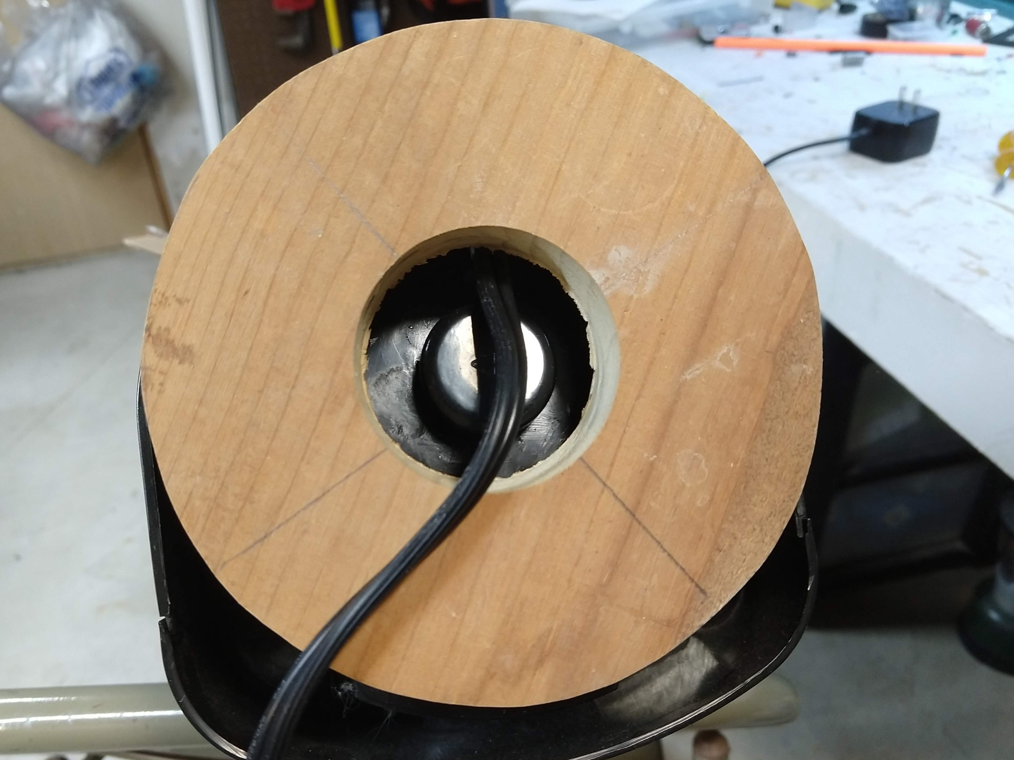
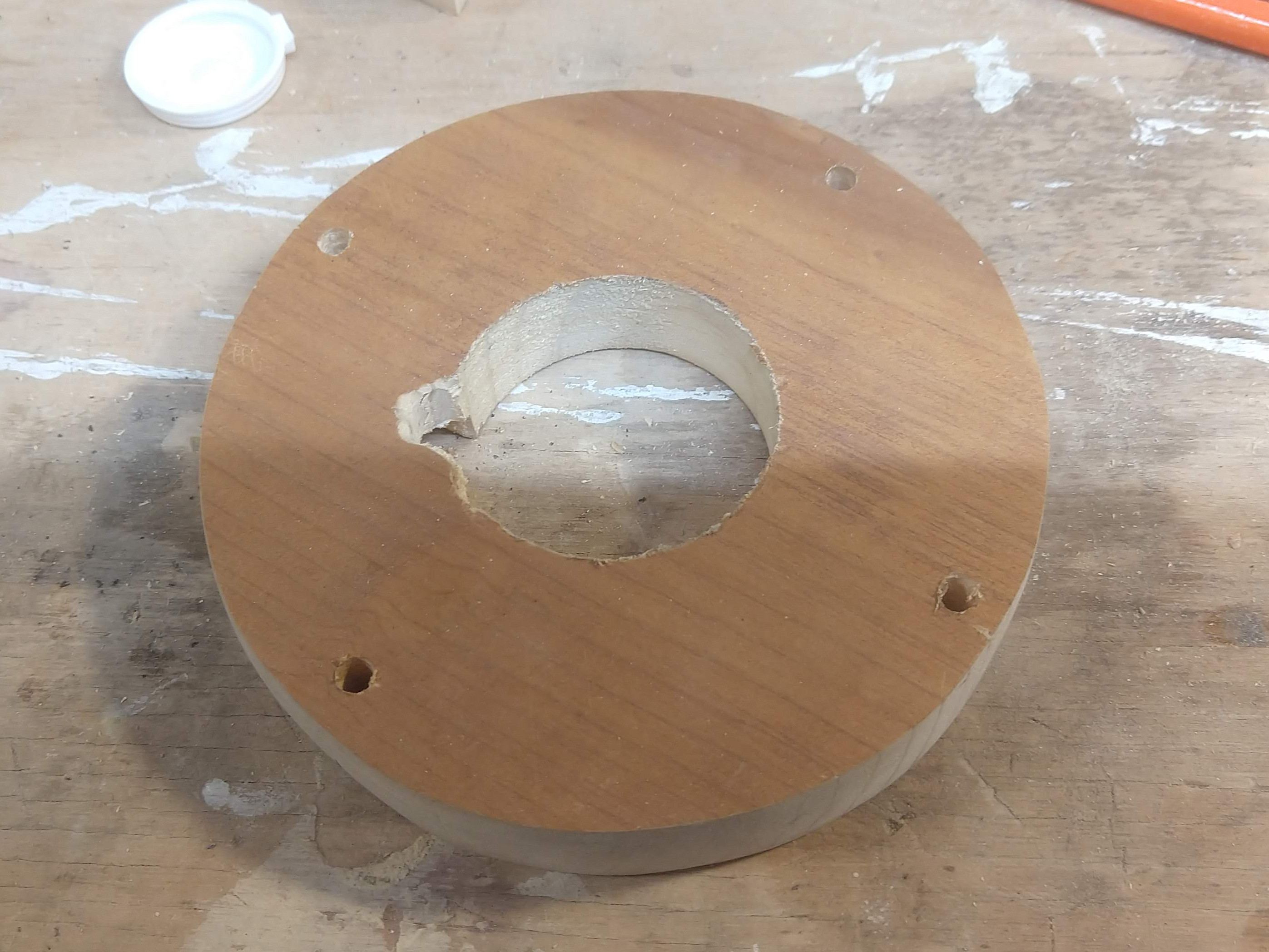
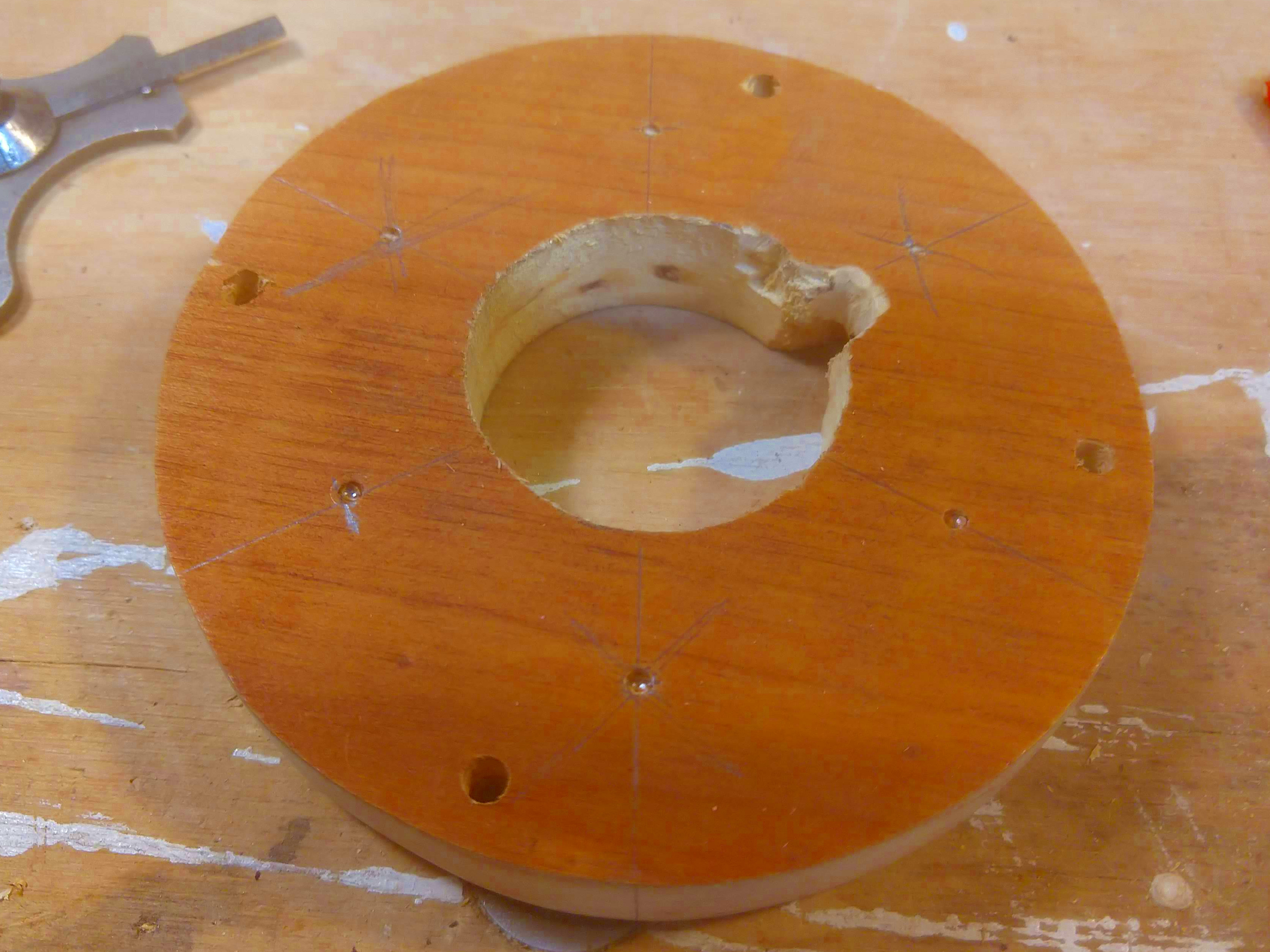
That’s probably right, except I can’t check due to the cord and a case protrusion on the bottom of the fan. I need an inch-ish hole center-ish. Being precise here is unnecessary, if someone is looking at the bottom of the fan, they’re doing it wrong. I really should get some forstner bits, until then I guess I’ll just use a hole saw. I remember The Hole Saw Incident, last time I put a hole saw in the drill press. After changing my pants, I swore to myself I would never do that again. At least this time the hole is a few times smaller.
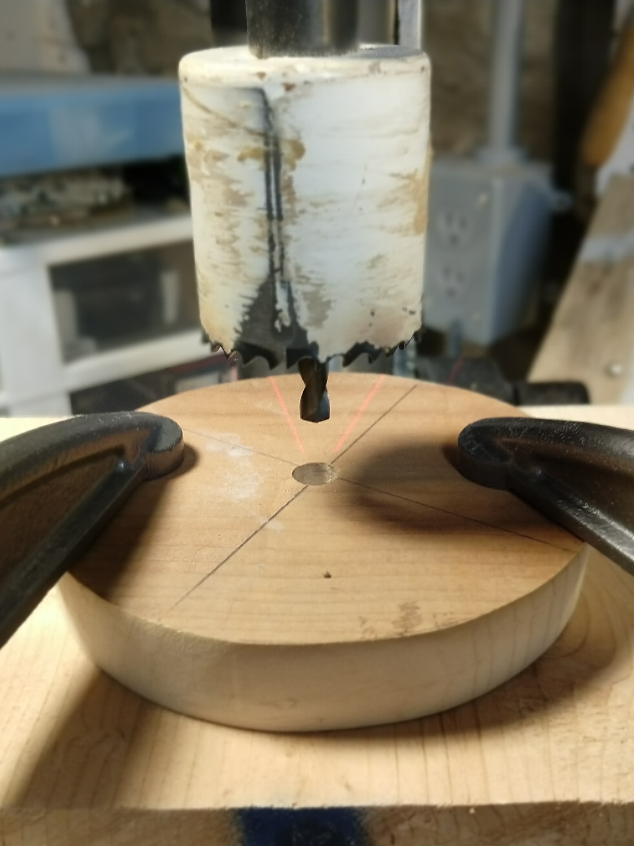
No I don’t know why I drilled a hole before using the mole saw.
Unfortunately, the cord is still getting in the way.
I don’t want to make the ring too narrow. Looks like it’s time to chuck dumb stuff in the drill press again! I’ve got this milling bit meant for a dremel I’ve been wanting to use. The drill press on maximum speed is within dremel speed range, I’ll just have to be extra careful.
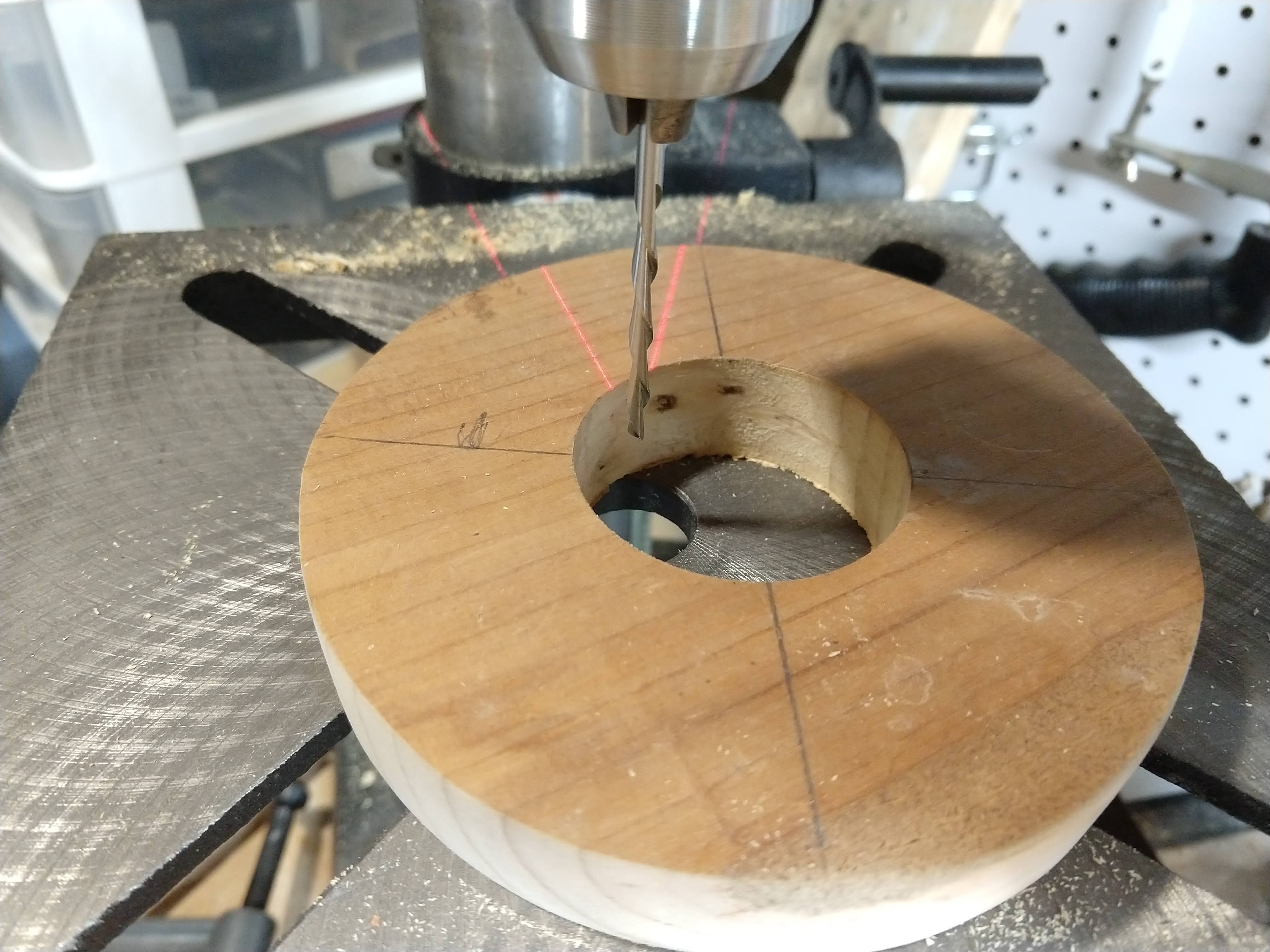
Ok, that was less scary than the Hole Saw Incident. Only cutting about an 1/8th inch deep and moving slowing mostly worked. It had a tendency to grab and pull along the grain, but that’s inside where it will never be seen. Not even by you.
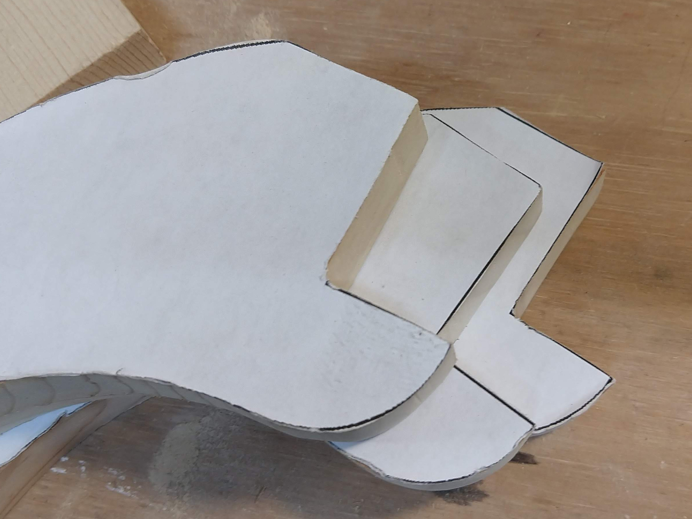
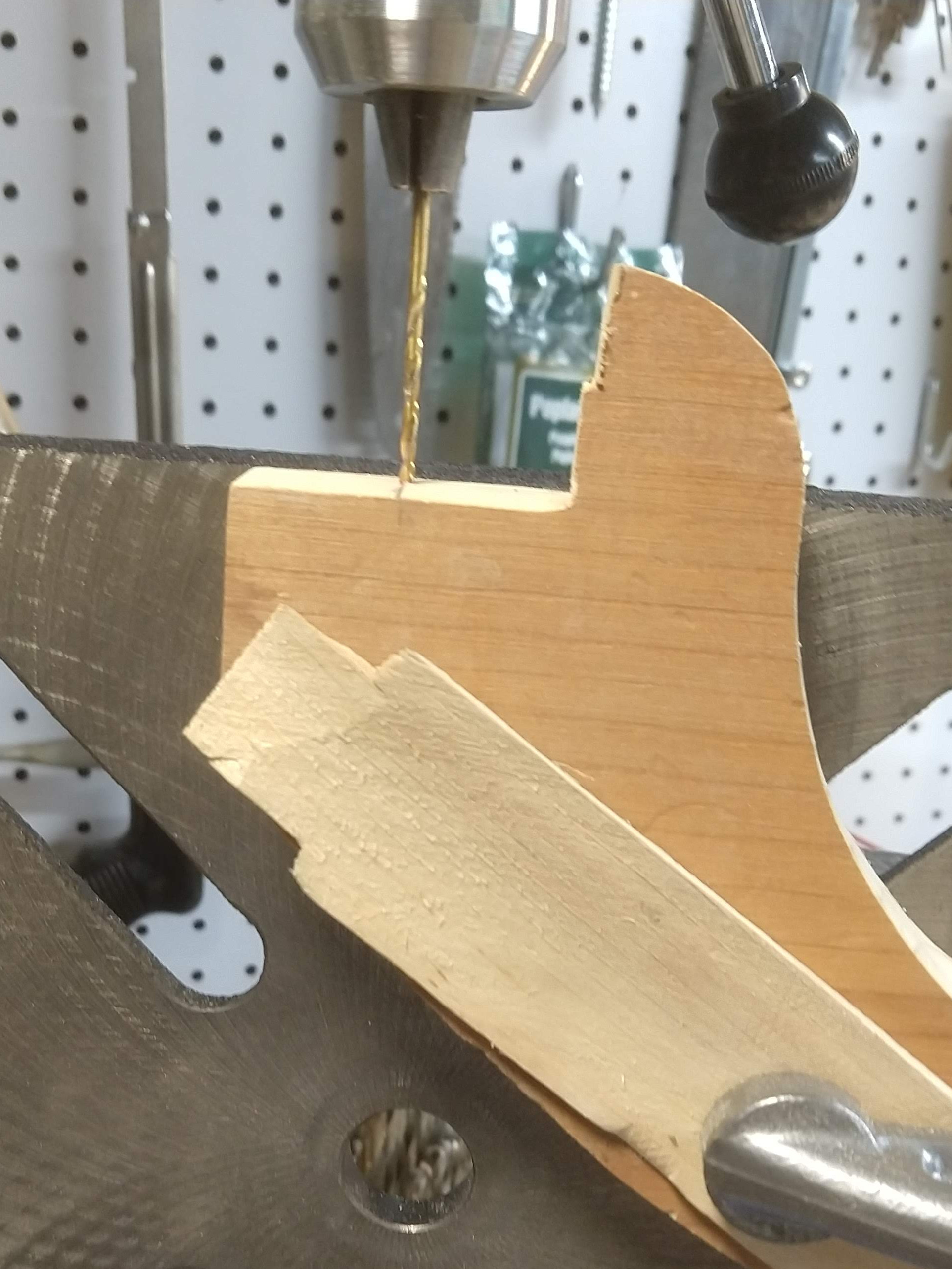
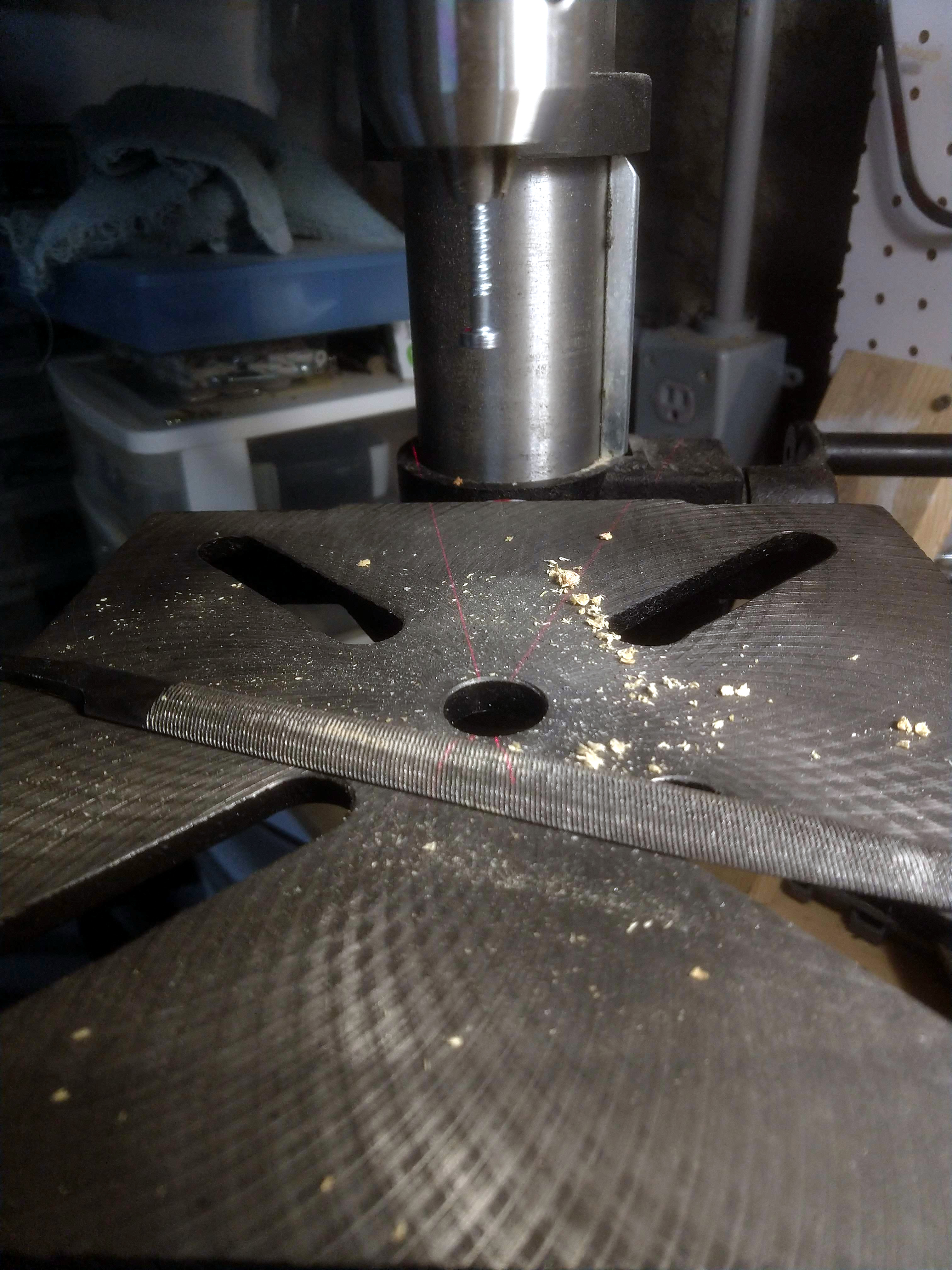
Now to connect the legs, I’ve pretty much committed to the connection method in the drawing now, So I’ll just knock out the corners from the legs.
Now we get some trickier bits. We’ve got to use the four mounting points on the fan for the ring, without getting in the way of mounting the three legs. I’m going to take a benadryl now in preparation for the Math I feel coming on. While that get started, I’ll mark out the holes using the old base and a punch. Now the fan uses the Acursed Metric, specifically 4mm in this case, so I’ll just drill these out to whatever Blessed SAE size is slightly bigger (either 11/64 or 7/32 I didn’t really pay attention to what I grabbed).
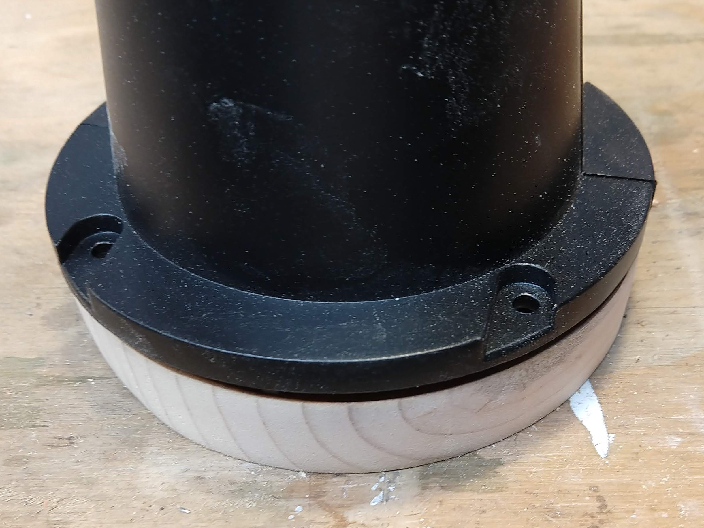
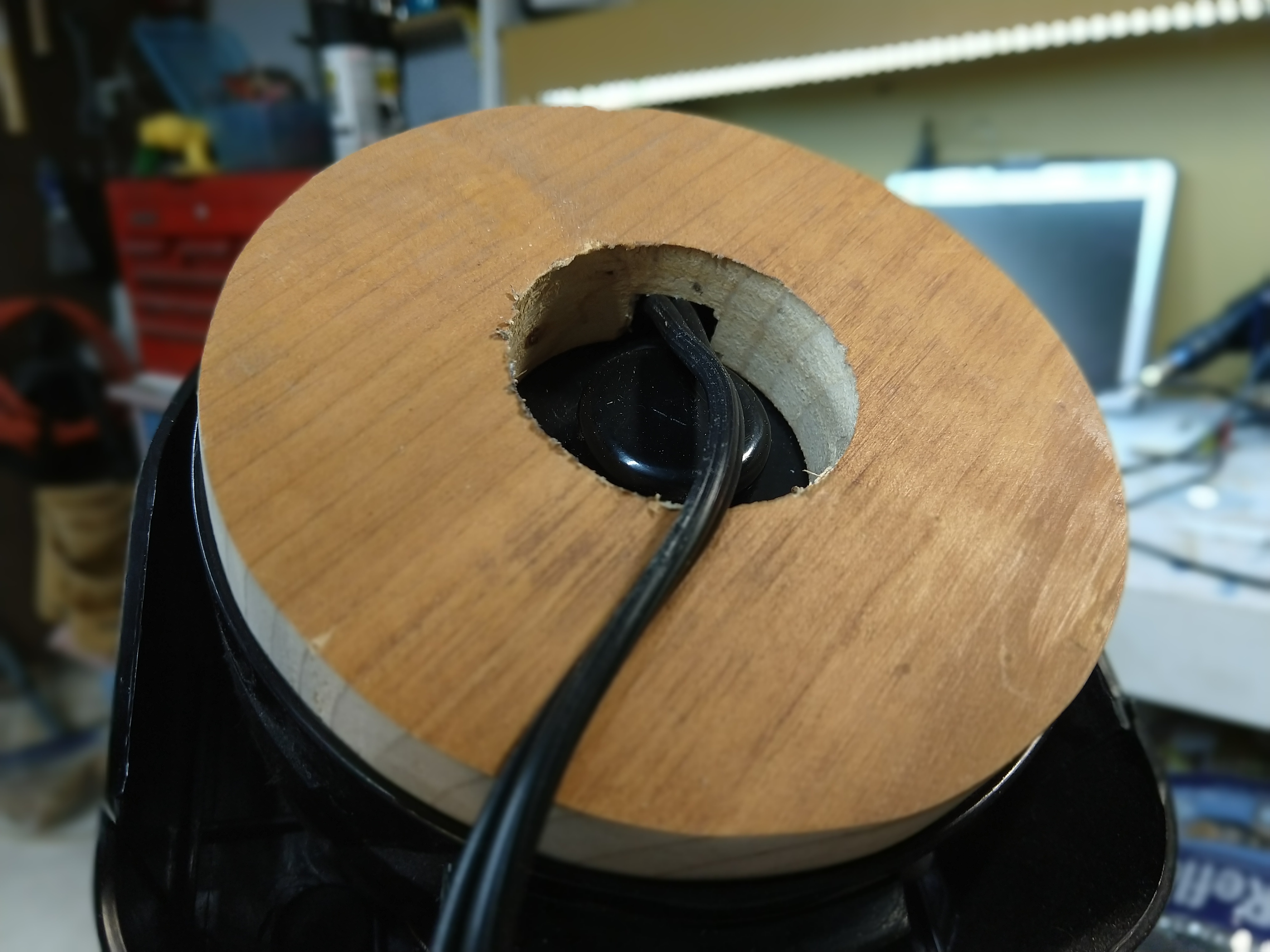
I smidge of filing to fit over the fan case, and now. . .
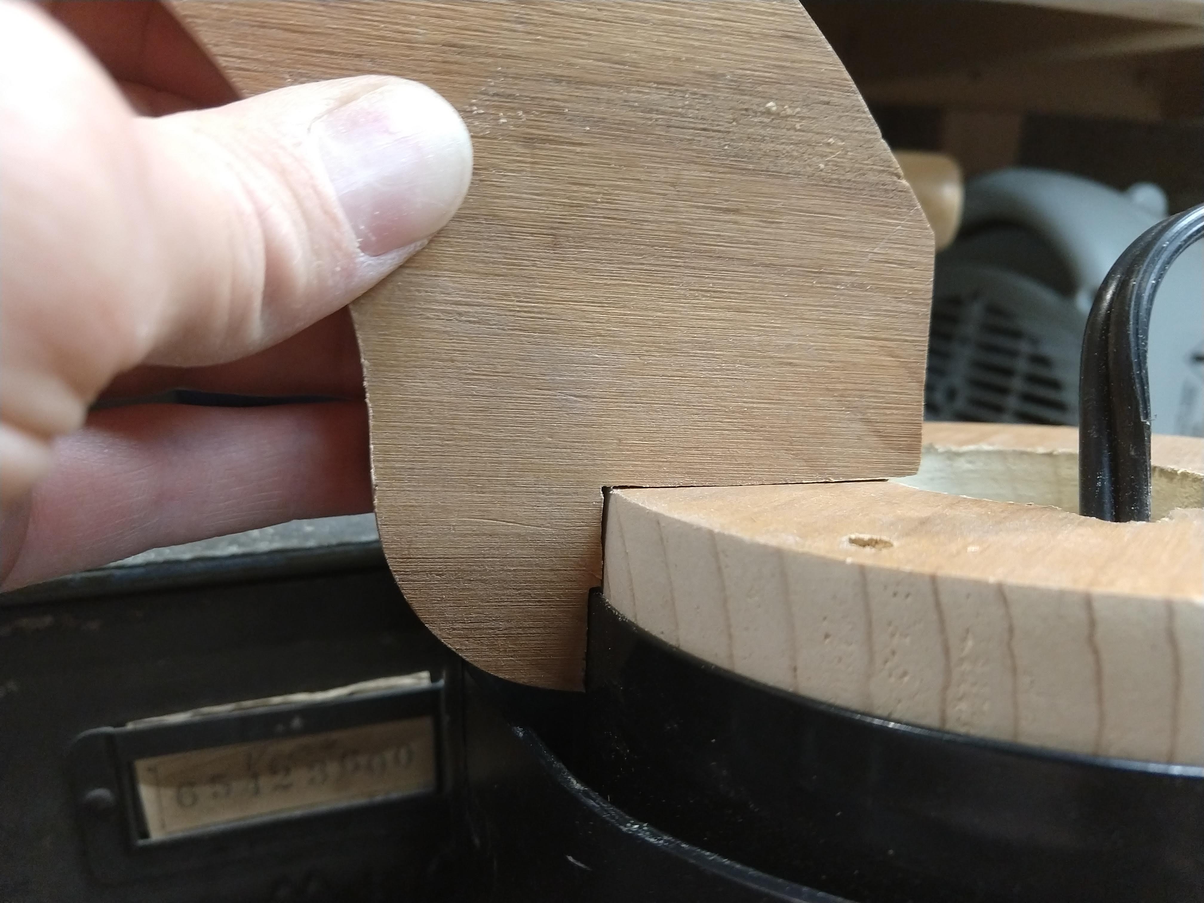
That should be good enough. Yes I know, it’s not perfect since one is a curve, and one is a flat, but frell it, I’ve been doing this all day. If I had a mill or a something I suppose I could curve the inside of the legs.. Oh, I do have that 4" hole saw. . . no, I didn’t bring a change of underwear into the shop to day.
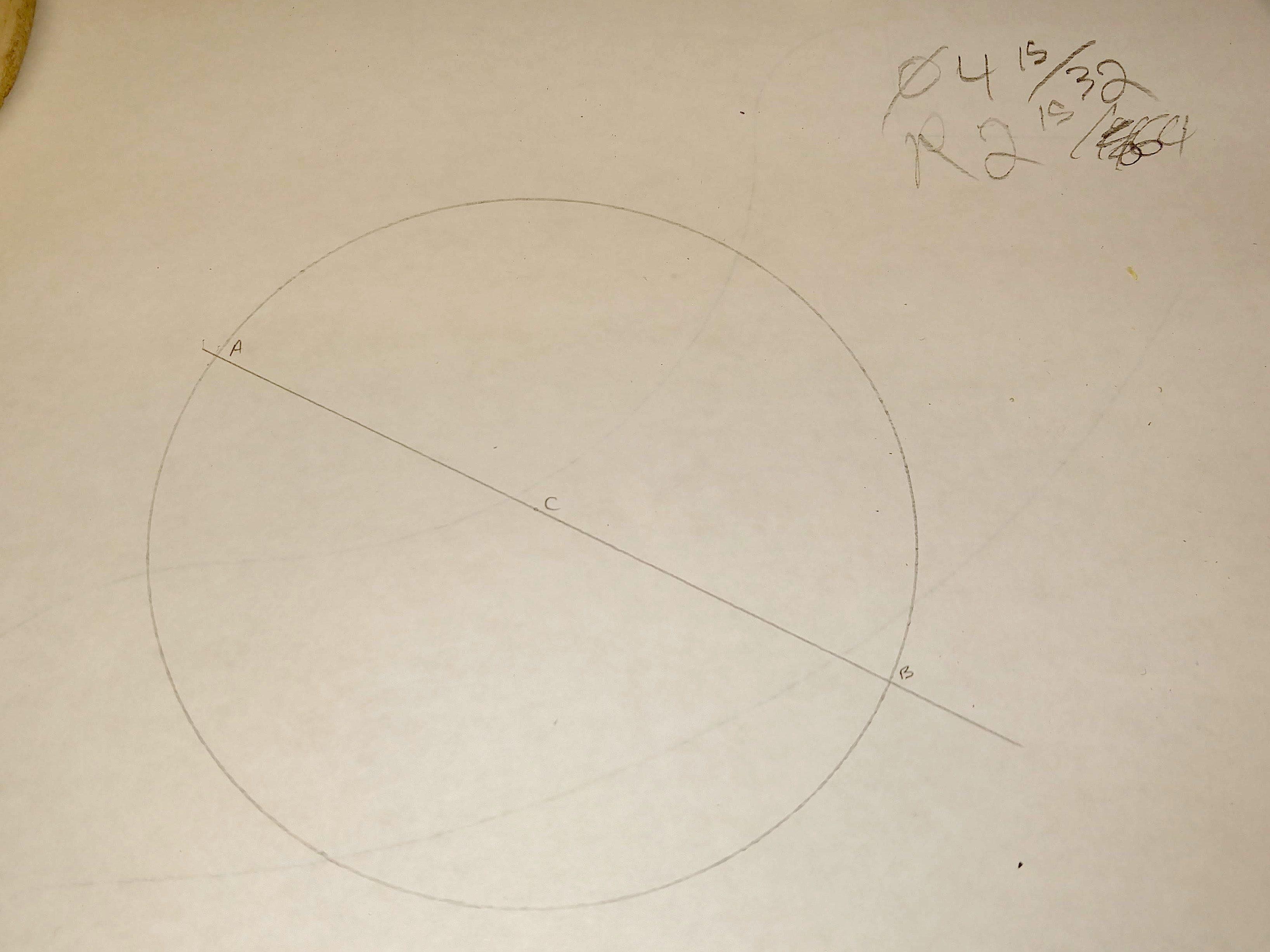
Now the the anti-allergies have kicked in, lets plot out the leg attachments. We have four points and three points that need to be spaced evenly, but without repeating points. If sockets have taught me anything, that means I need 12 points. I don’t actually need all twelve, I just need three more. Lets start with arbitrary diameter line.
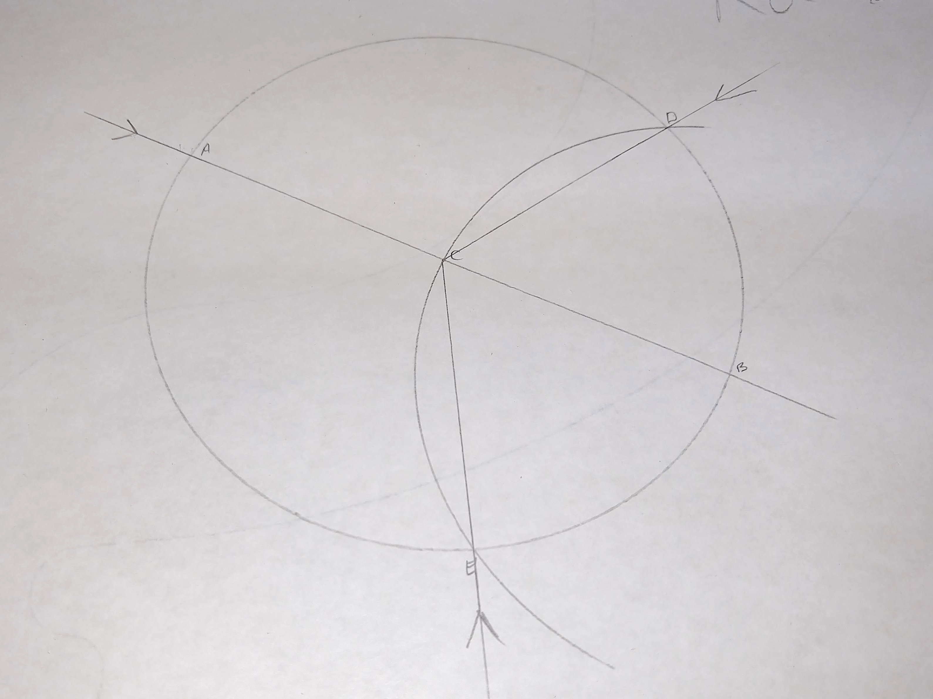
Then lets use that line’s intersection with the circumference as a center for another circle, of the same radius. The intersection of the circles are two of our new three points, the other end of the original diameter is the third. In this case {A, D, E}.
To make sure I don’t get the legs interfering with the mounting screws I’ll set the ring on the drawing, spin it around until the marks line up nicely, and mark some lines down. Ok, it also helps if you check to make sure the cord was not in the way too, so I’ll spin 60° and try again.
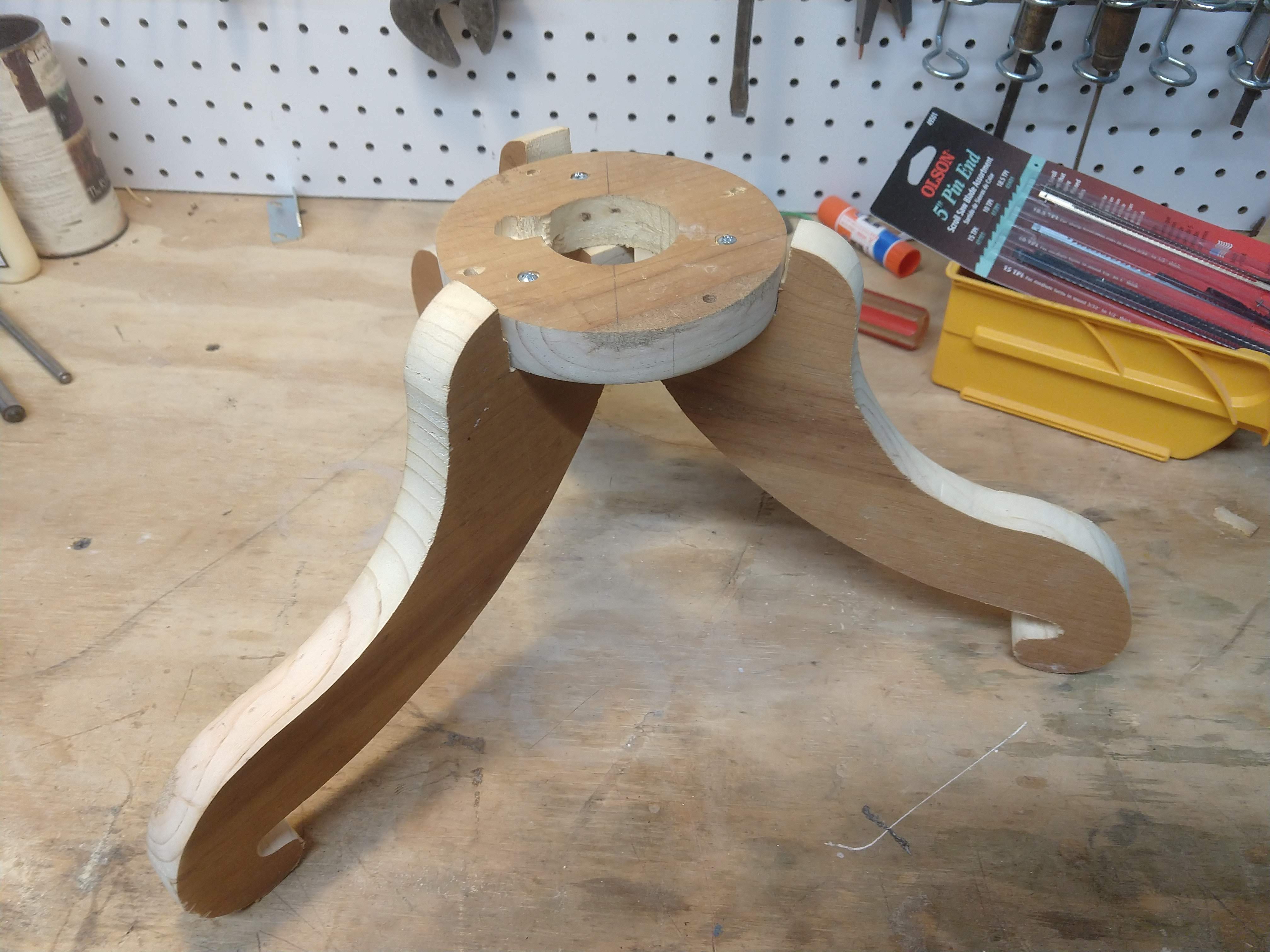
I want to put the dowels in to hold the legs on, but I’m also terrified of getting the holes in the wrong place. For now I’ll just use three #6 1 1/2" wood screws where the dowels should be since the heads fit into a 1/4" hole6. This would be easier if the makers of my drill press had considered 90° to be a valid angle, I’ll make it work.
Stop. Assemble time.
Dang it.
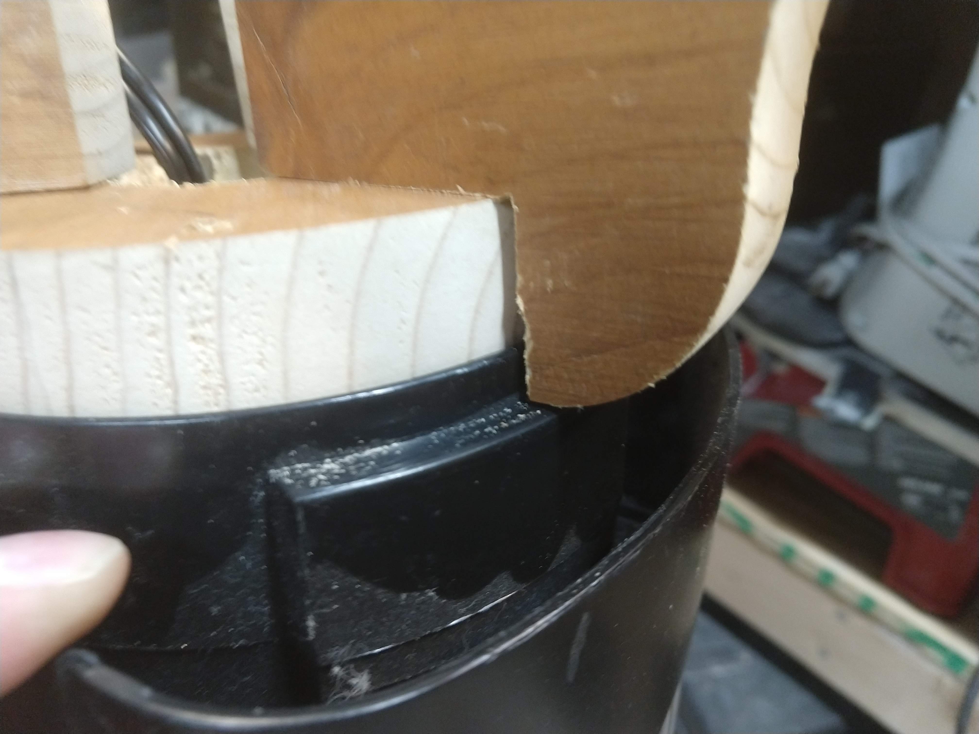
Who put that there. What idiot didn’t notice that when taking measurements. Oh. This is why you should delegate blame tasks. Well, this is why I have files.
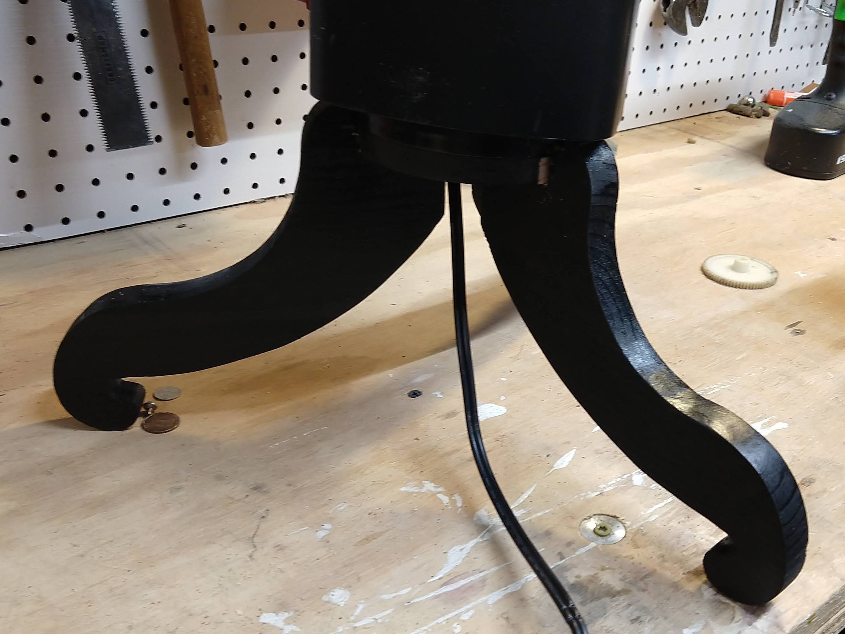
Woo!. Close enough for now, I’ll just have to replace the screws with dowels and paint it, but for the time being I need to use it.
Retrospective
It needs some more strength. Originally I’d planned on adding screws from the back of the legs locking together in a central dowel, but that is a bit complicated, maybe I’ll try it sometime. More realistically I’ll add a screw diagonally into each leg through the ring. That’ll at least add some resistance to downward forces.
Better measuring during planning. you saw that one leg I had to adjust due to the motor housing, what you didn’t see was that I had to trim down the height of the legs. Apparently the bottom of the fan is not level, so as it spun around it would sometimes come in contact with the top of the legs.
Joining to curves. If I were to make it again I’d make the ring not a circle, it would be slightly larger with flat spots for the legs to connect to. As of now the legs can be twisted around.
Better marking of the mounting holes. Something went wrong and only two of the holes will line up at a time. I guess it twisted some when I marked them. Possibly the mounting holes are not equally spaced and I didn’t get them lined up the right way when I made the cord hole.
This is what I get for trying to use a glue meant for plastic. I’ve never got the putty stick type epoxies to mix properly. I should have just used the generic two part epoxy. ↩︎
Contrary to popular belief, I’m not being completely arbitrary here. There are practical reasons for choosing speficially three legs, if I used any more than that I’d have to actually get them to be the same length. Also, my house was not quite built to exacting specifications, and as such the floors lack the usually desired planar qualities. Just imagine how wobbly the old infinite-leg base was. I would get into the how in an N-dimensional space you’d want N legs, but I can feel my Math allergy acting up already. ↩︎
Since I’m lacking a French Curve the easy way to get that swirly shape is only draw 90° arcs with the compass decreasing/increasing the radius a fairly consistent amount. I tried to stick with doubling/halving except where I couldn’t. ↩︎
Yes, yes, that spot is going to be the weakest no matter what since it’s the thinnest. But wood (usually) breaks along the grain, so having it line up with the weakest part seems like tempting fate. ↩︎
±1 Smidge ↩︎
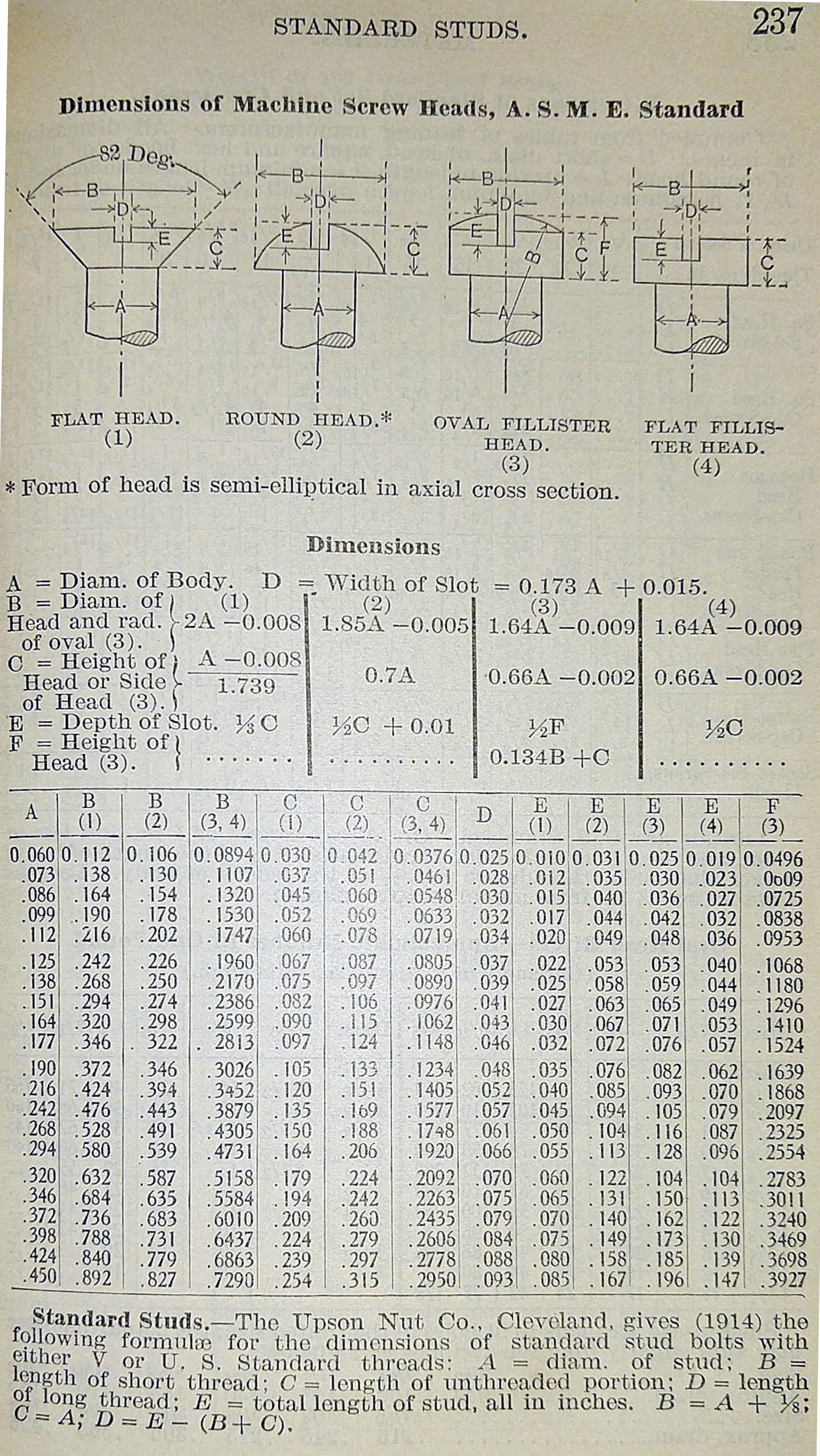
Well they could if they had Cheese Heads7. Good thing they do, I’ll not admit to claims otherwise. ↩︎
My Mechanical Engineer’s Pocket Book (9th Ed, 1916)8 calls them Flat Fillister, but “Cheese Head” is more fun for me. ↩︎
A note on that book, it’s old enough that it’s public domain (so I can include pictures here), and the standards in it are close enough for my work. The machine and wood screws seem to be ±2 thou compared to modern tables. ↩︎