It seemed like a great idea, but the plan had some holes.
Posted January 4, 2022
Air Return Venthttps://caleb-vincent.io/post/2022-01-03-air-return/
My house has a couple places where an old-style wooden grate used to be. I’ve been putting off making them for some time, cutting all the notches to fit the grid together just seemed tedious.
However, then I came across these videos and had an idea—a wonderful, awful idea.
I figured I could make an air return grate of a similar style. Making a ton of cuts would be tedious, but surely drilling 395 linear inches of holes won’t be?
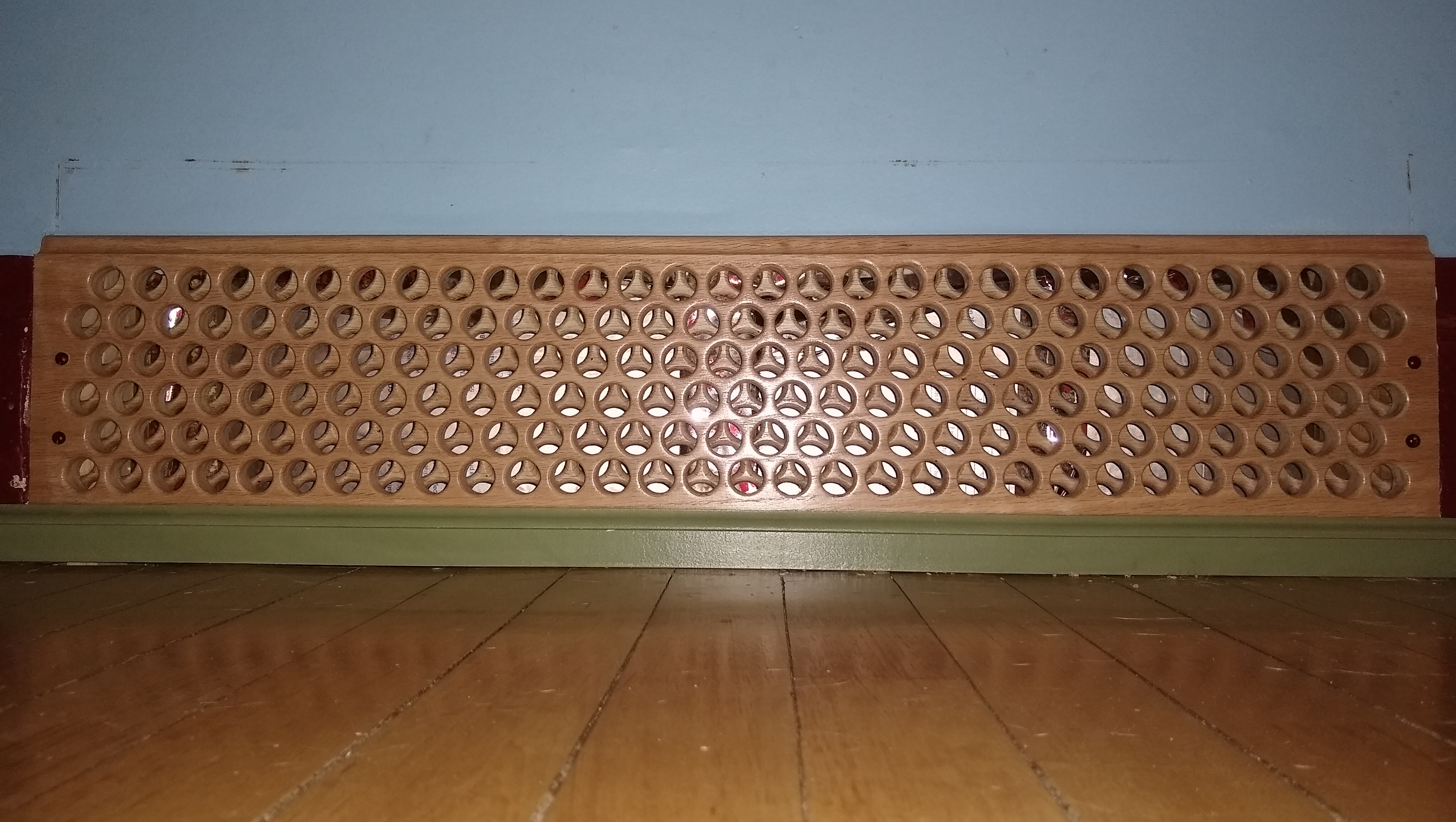
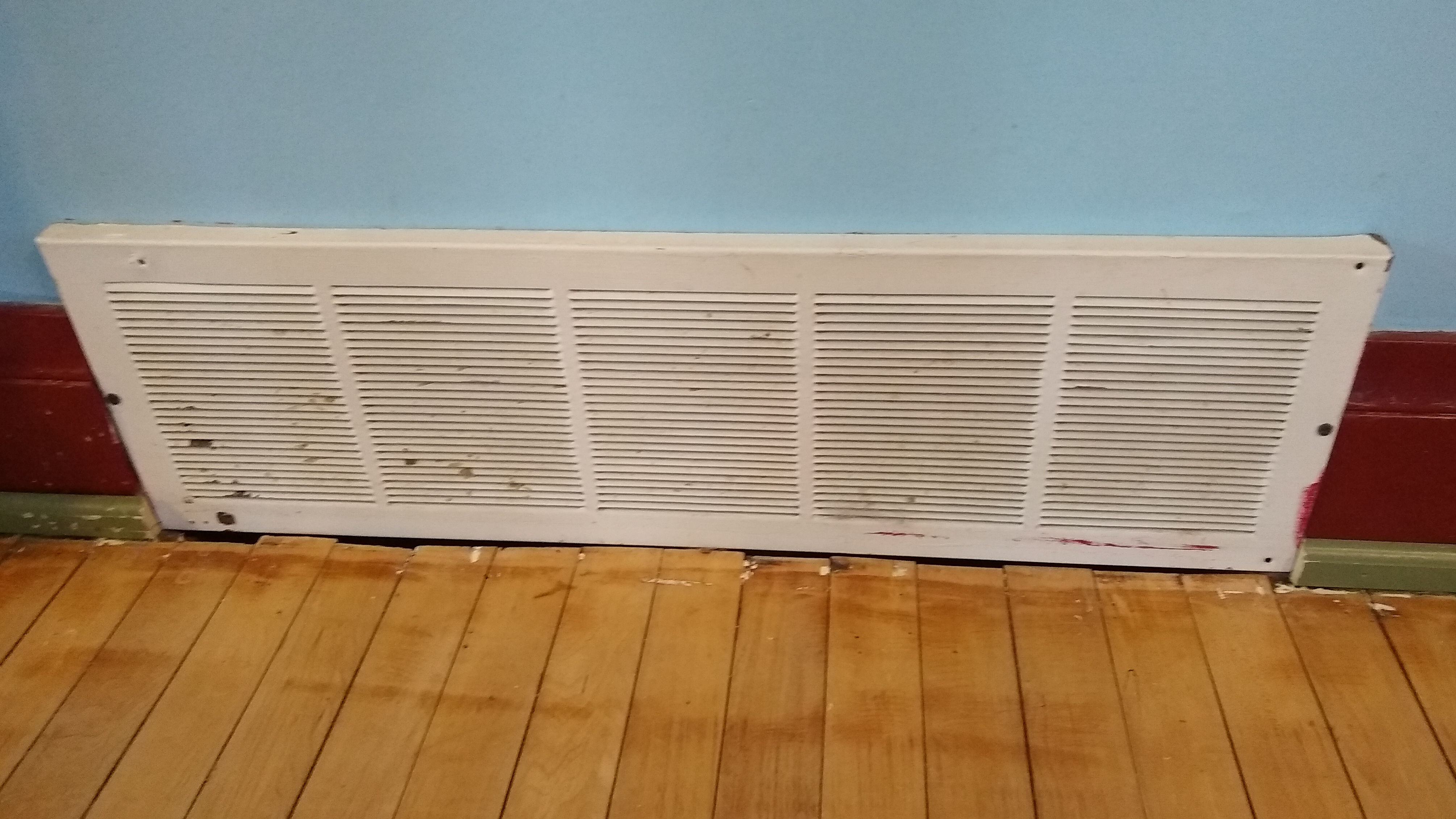
This is the vent that was present when we bought the house, a newish installation of similar style to the other vents. The hole appears to be the same age as the oldest ductwork, and there is no sign of a previous hole in the floor, so this may have originally been a metal grate, or a wooden one. The other end of the house has a much larger patch in the floor that was likely a wooden grate, this will be a test run.
Planning
The referenced video drills holes from the front and back of a single board, this leaves marks from point of the forstner bit in the middle of each hole, and just the rear part just looks a bit rough. I plan on making it from two pieces, so that tool marks won’t be visible, and I can round the internal edges to give more room for airflow.
The grate will be made of oak, the front piece: ¾″, the back: ½″. The ¾″ is thick enough to sit flush with the baseboard, and the ½″ is thin enough to fit between the studs and the baseboard. The back is offset down slightly to fit in the existing hole while the front covers it. The additional space between the bottom row of holes and the edge will be covered by the baseboard shoe. The holes are ¾″ diameter, as this is usually the size of the grid of the traditional wooden grates. The holes on the front have a ⅛″ roundover, all others are ¼″. The top edge has a ¼″ ogee to better blend in with the baseboard.
Making the Front
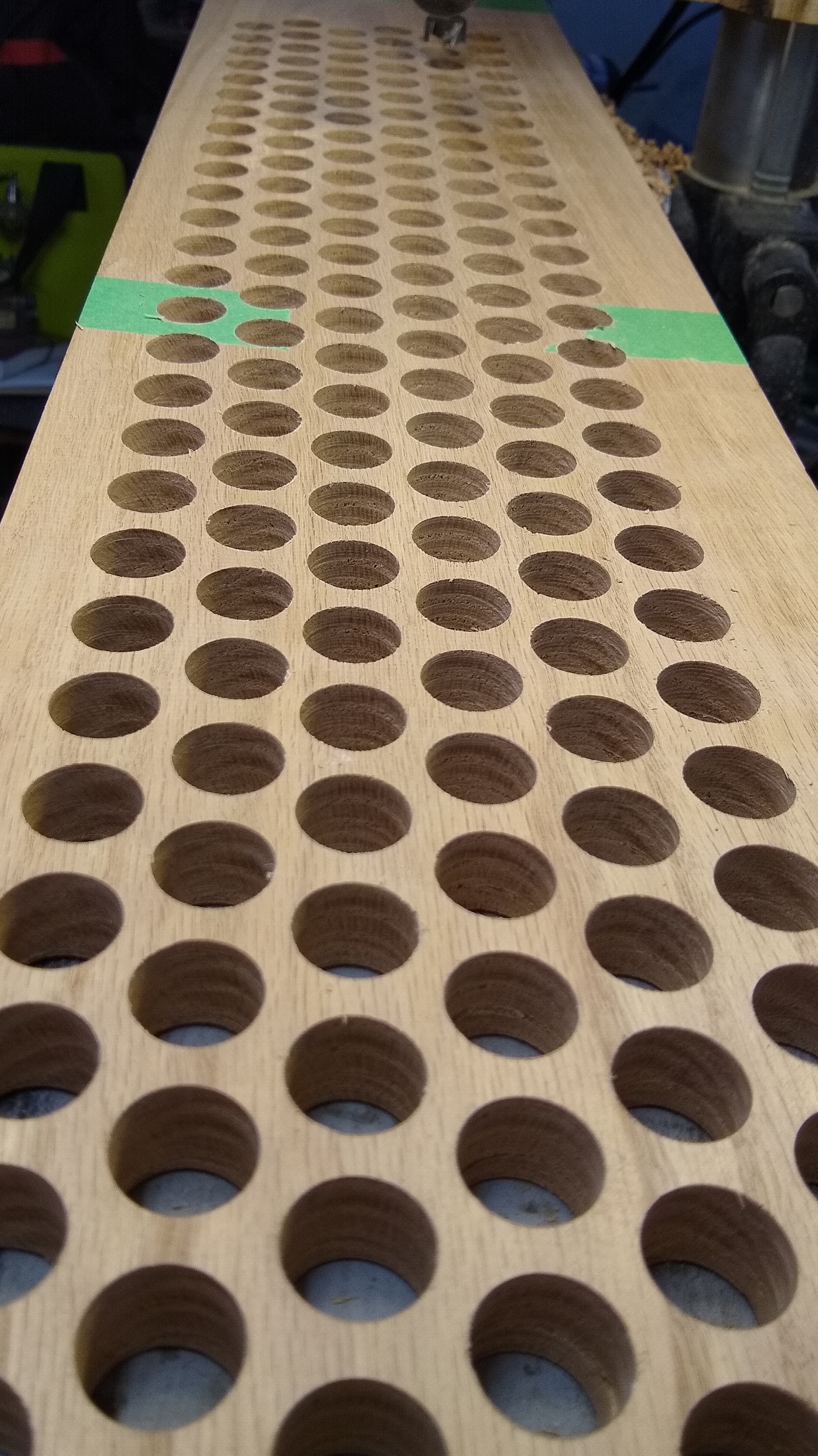
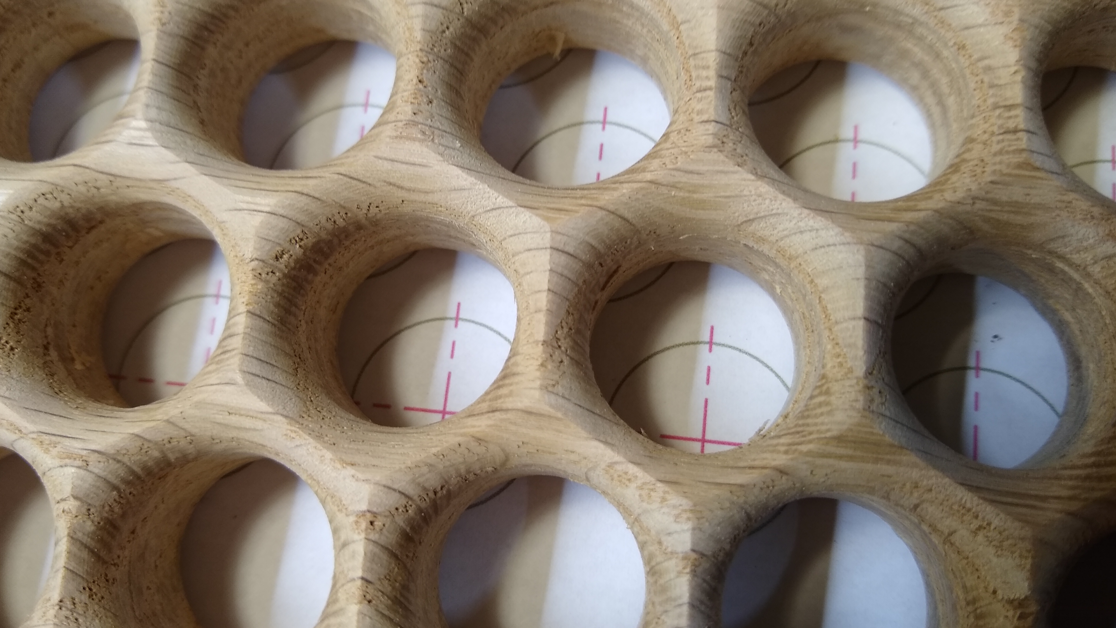
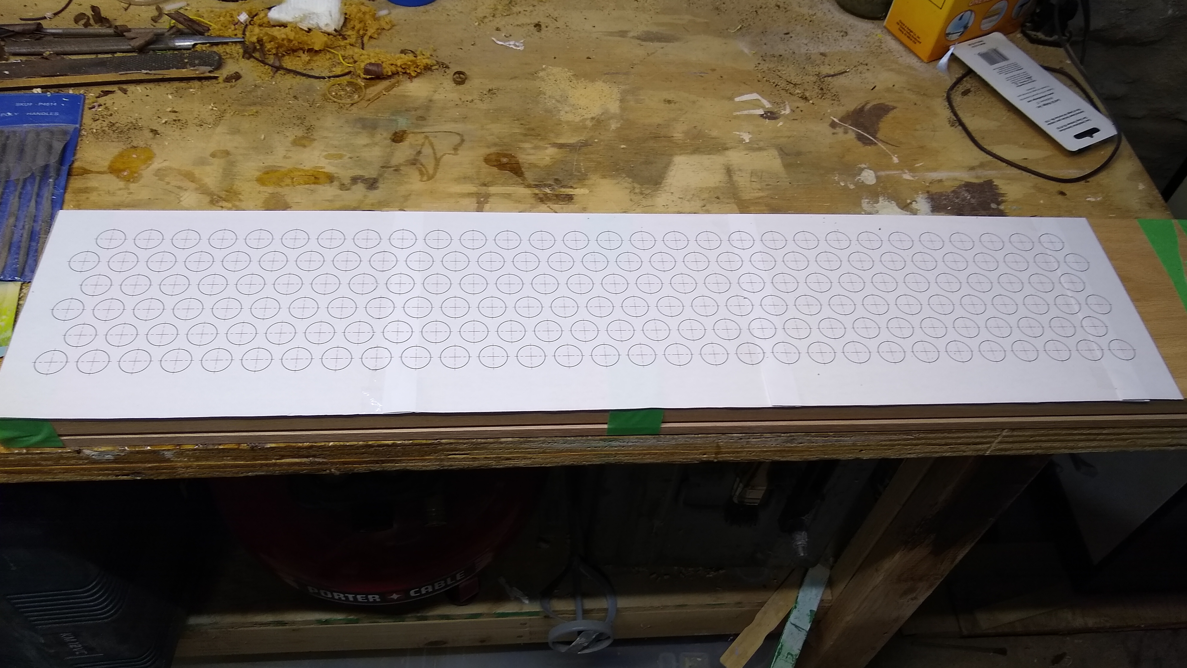
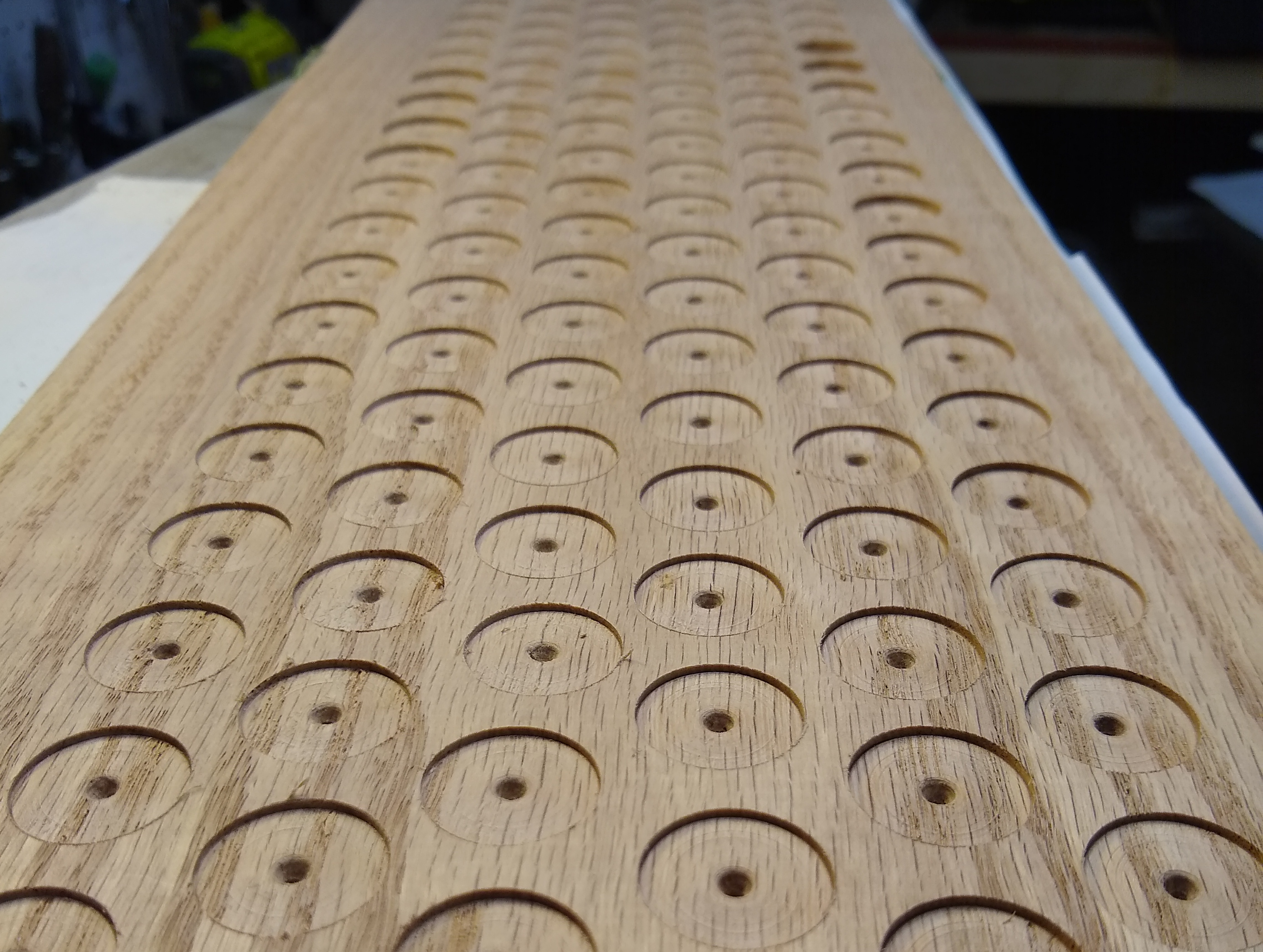
In interest of my time and sanity, I printed out the hole locations and glued the paper to the boards. This pictures both the boards being lined up together to be drilled, this turned out to be impractical.
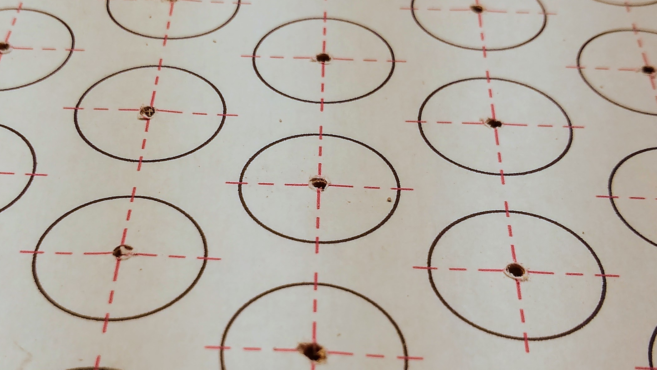
Each hole location had a pilot hole drilled though so that both sides could be located.
The pilot hole had to be smaller than the center spur on the forstner bit, but as large as possible to reduce deflection. If the hole is too large, the outer cutting surfaces of the forstner bit will come into contact first, and the piece will have to be manually located.
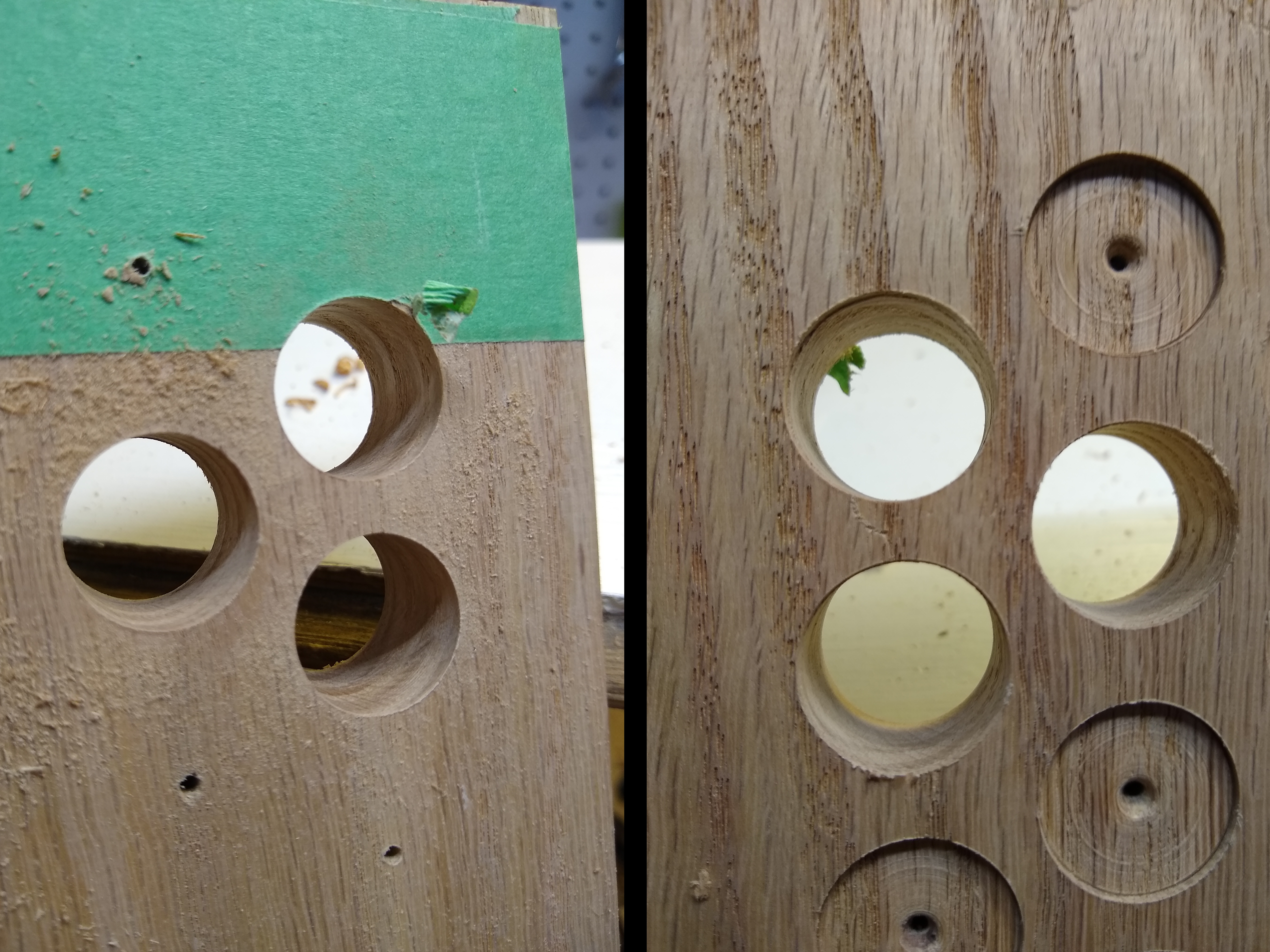
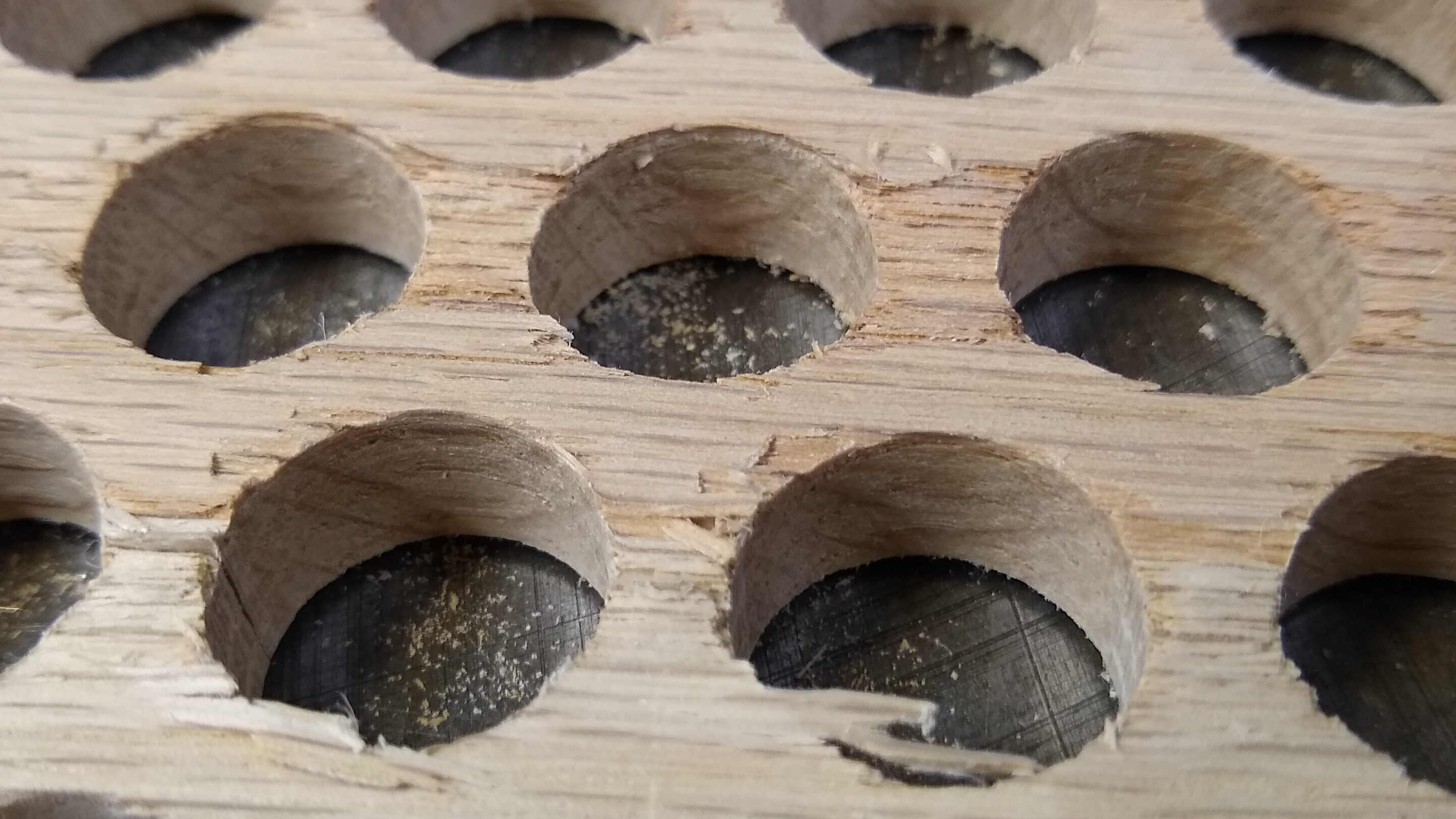
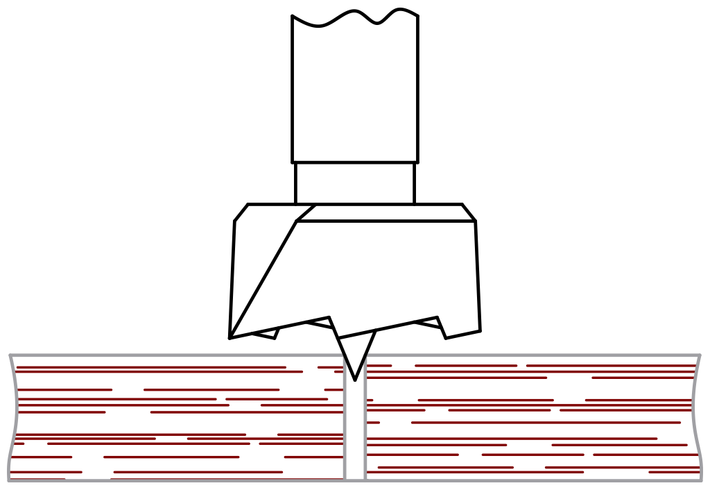
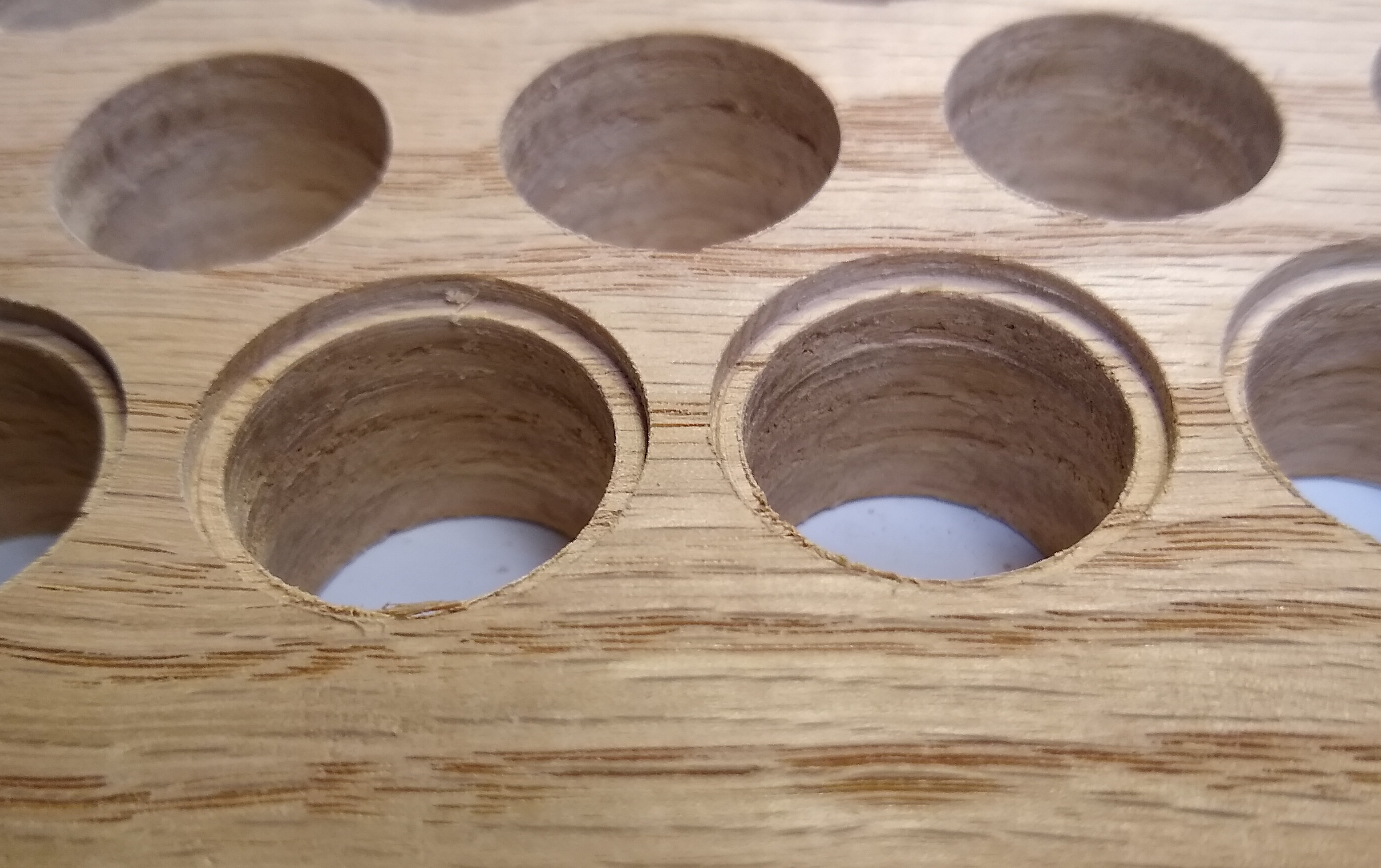
First a full-size hole is drilled part way from the back side. The idea is to prevent tear-out, whenever the forstner bit exits the wood there is a chance of pieces chipping off. If the hole is drilled through from both sides, the bit never exits, and doesn’t tear-out. Always remember to check that you grabbed the correct drill bit.
The double-drilling seems to have worked—holes look clean, and they appear to be lined up.
After completing the rest of the board, there are still a few instances of tear-out, but since the back was drilled first, it should be (mostly) hidden. But that should be hid by the round over, and this is why I started on the back side.
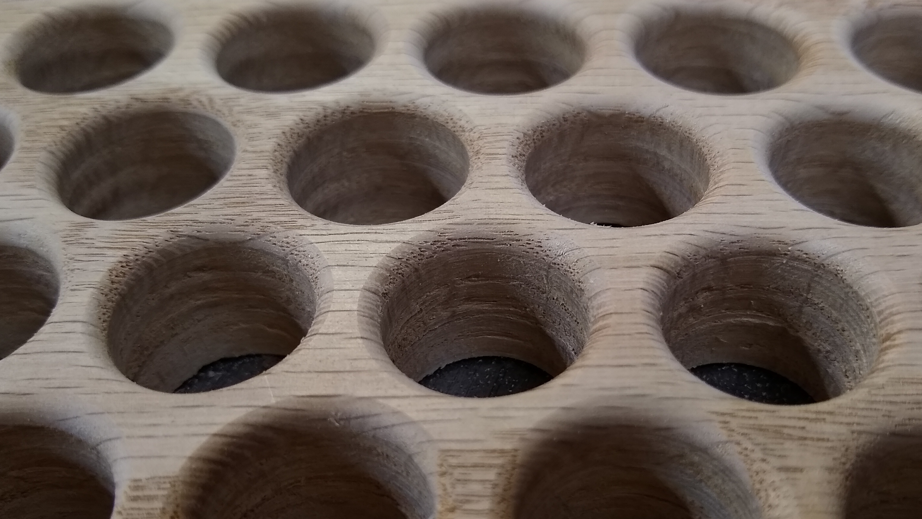
Some time later… half the holes are drilled through. A similar activity will have to be performed on the back piece.
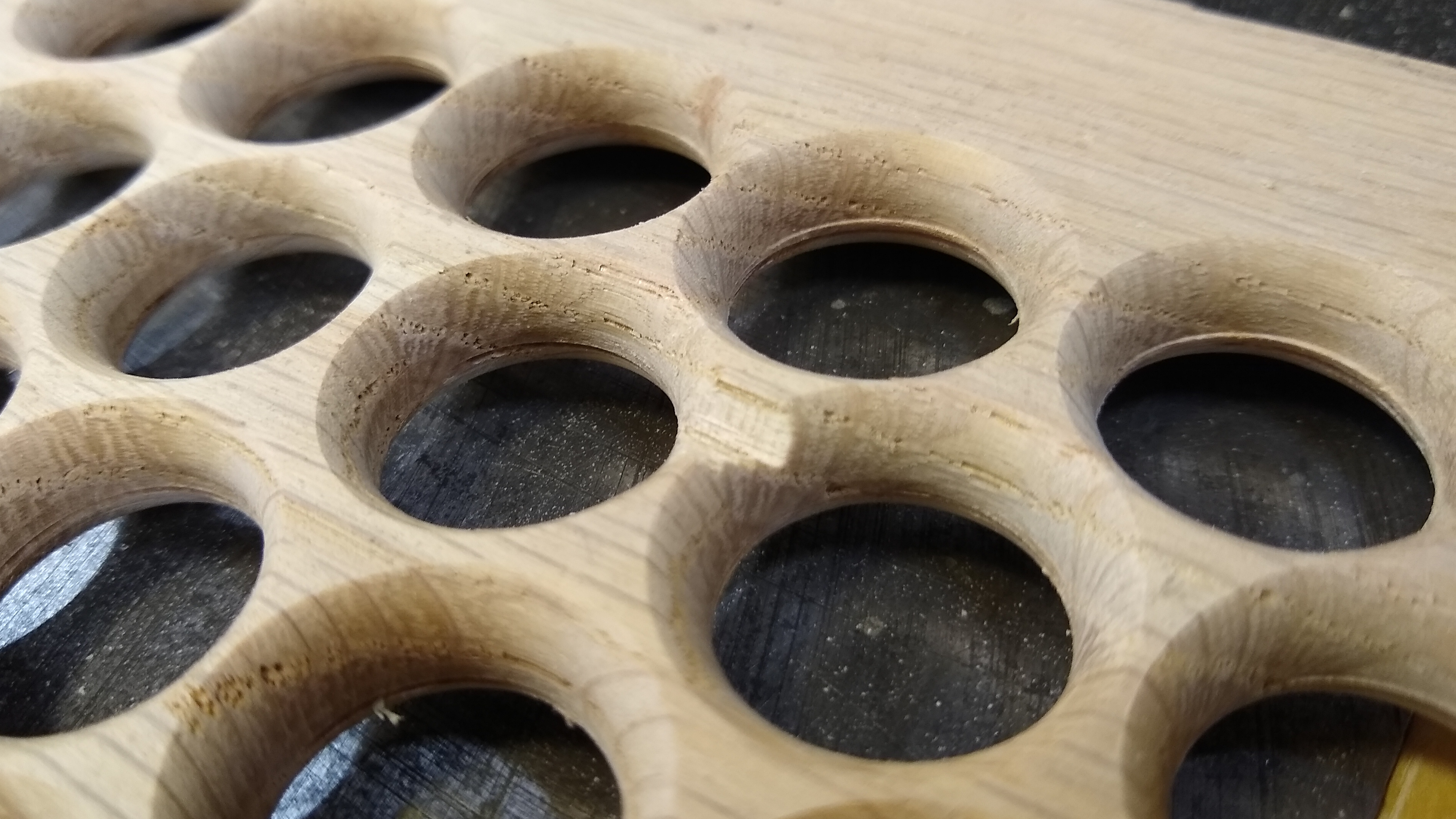
The ⅛″ roundover on the front seems to work out well, no further comments.
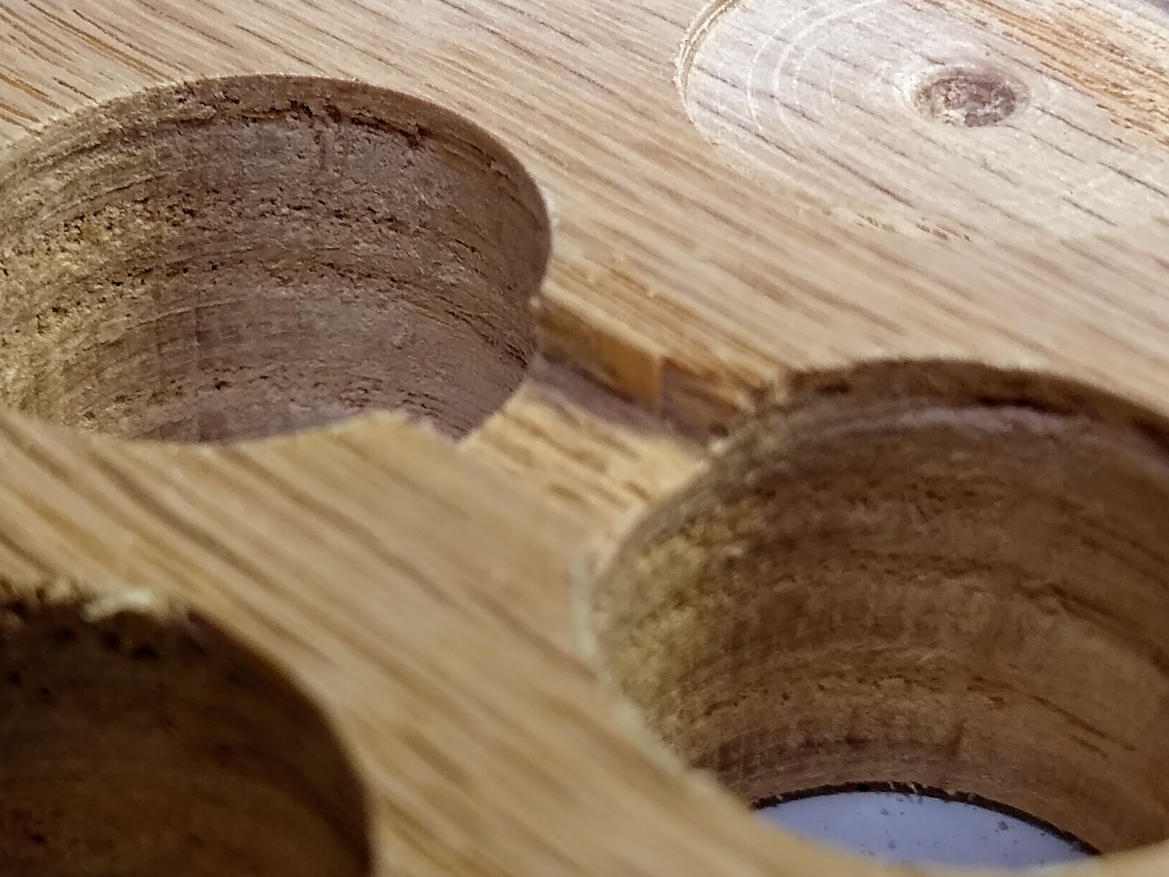
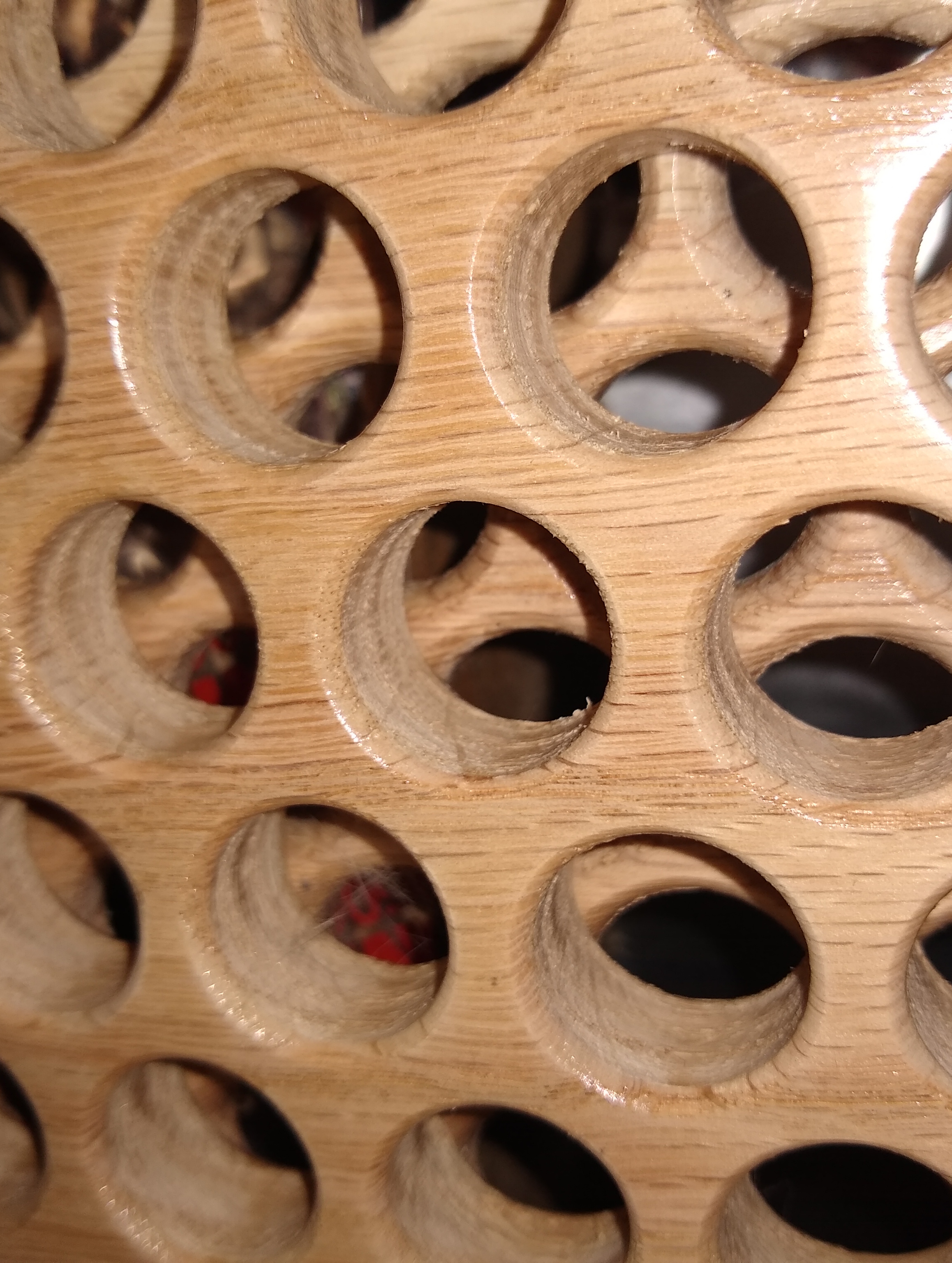
The back ¼″ roundovers also worked out pretty much without problem. My test left a larger flat at the tripoint between the holes. I had been intending to glue the two boards together, but looks like another method will have to be used.
Making the Back
Second piece, same previous. A second layout paper was printed, with the additional holes needed to ensure that all the holes on the front have the same look.
In interest of “science” I didn’t use a pilot hole or double drilling on the back piece. A simple punch served to align the forstner bit. Starting with the forstner also worked, but took much more effort to get aligned.
There was some tear-out on the back, but that shouldn’t be visible unless you get your face right up in there.
Both sides received the ¼″ roundover, which didn’t go as well as the first, but was okay. Sometimes the router would jerk, and sometimes a chip would break off, this was further complicated by the board’s cupping. Only a couple of these might be visible in the final build.
Assembly
Prior to assembly, much sanding must occur. Far too much sanding. Sanding made worse by the fact that I don’t seem to have a foam sanding block anywhere on the premise. So after trying to get in all these curves by hand, and then resorting to a dremel with a sanding drum, I called it close good enough.
Some screws in from the back hold it together, in the corners, and then a couple in the middle overlapping tripoints.
Once given a coat (or two) of polyurethane, and assembled, it can get put in place. Usually I paint the inside of ducts flat black when visible, but in this case, it seemed… a bit much. There is visible reflective tape here, and I’m tempted to coat the whole inside of the visible wall with it.
Retrospective Thoughts
This is not even remotely materials-efficient, something like a third of the original board is on the floor when you’re done.
The double-drilling worked pretty well to prevent tear-out, but the first pass needed to be deeper, probably about half way though. The shallower the first pass is, the more likely chipping seems to be.
½″ (nominal) is too thin. With the ¼″ roundover the router bearing rides on the curve from the opposite side, so every pass is slightly larger than its opposite.
Plain-sawn ½″ oak boards cups badly and complicate the router usage—the edge holes get deeper than the center ones. Quarter-sawn would probably be better, but then you have to think about how expensive that big pile of wood chips is.
¾″ is a bit too thick. Just visually speaking, when mounted vertical it’s difficult to see the second layer.
The holes are a bit too small, maybe 1″ instead. Since this gets used in the bottom of a wall, it will always be at least person-feet away. This is made worse by the good viewing angle being well across the room
The single board approach has the advantage for airflow over this design. The opposing holes in a single board can be greater than half the depth, allowing them to overlap in the interior.
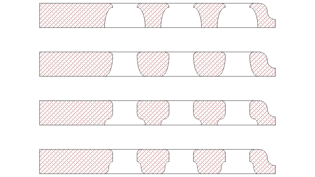
To give more internal visibility and airflow, alternate profiles could be used when cutting the back of the front board.Either the ellipse or the ogee would remove more material, however the width of the cut cannot be increased without affecting the contact points between the boards.
Conclusion
This design works, but could have some improvements
Both boards should be ⅝″ thick.
The gap between holes could be ~¹⁄₁₆″ smaller
Spherical depressions should be drilled ~¼″ deep into the back of the front board in the same locations as the holes though the back board—this gives a bit more visibility and airflow. Unfortunately, using a spherical bit in a drill press might be an adventure, and just using a forstner bit looks bad (bad enough I didn’t include an example).
If you have a CNC router, use it.
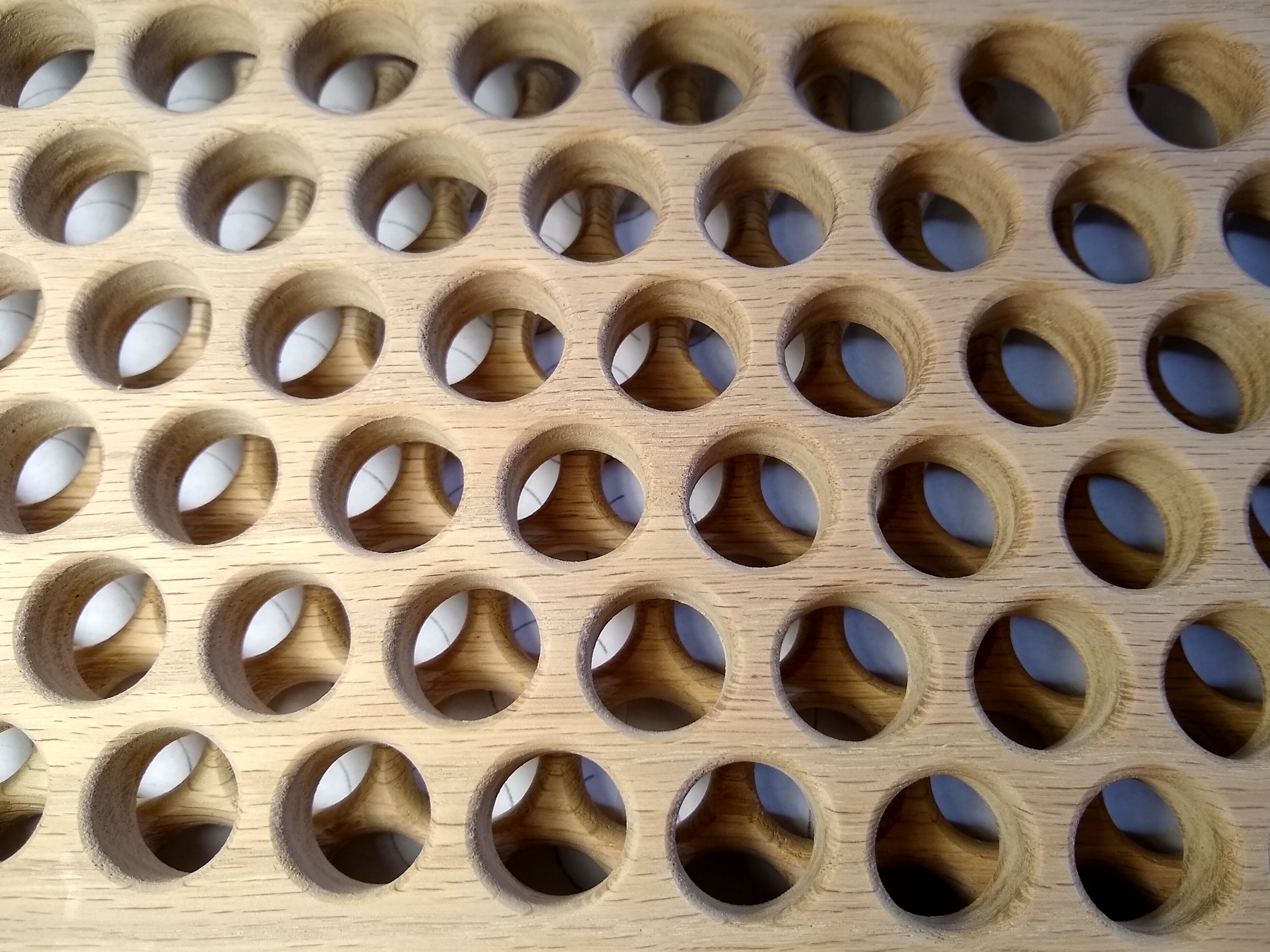
The current grate
Render of the current grate
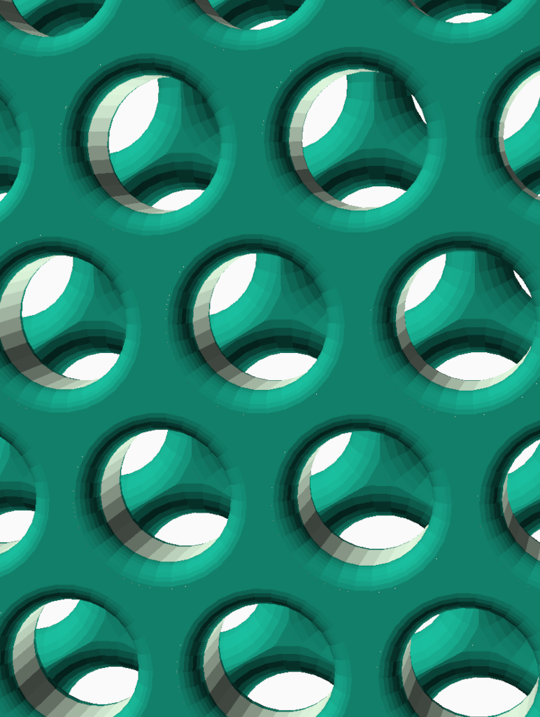
Render with 1″⌀ sphere removed ~¼″ from the front back
